Most deflections are repeated a number of times during the life of the piping system, since the deflections usually are produced by changes in temperature which occur each time the system is started and stopped, and from predictable variations in the way, the system is used. Repetitions can also occur as a result of repetitive mechanical movements and from vibrations. Each time a deflection occurs it is a CYCLE. The number of cycles is important to assure the proper design of the pipe expansion joint since each design has a finite, but predictable life.
Vibrations which cause repetitive deflections can cause premature failure of a pipe expansion joint. Even though these deflections may be small in magnitude, they usually accumulate huge numbers of cycles in a short period of time. Since the bellows are metallic structures, they have specific and predictable resonant frequencies, like the pitch of a tuning fork. When driven by outside vibrations of the same frequencies (or harmonics of them), they can magnify the incoming deflections until they exceed the yield strength of the bellows material and induce early fatigue failure. When a piping system is known to have equipment which can produce vibrations, such as pumps, fans, and other motor or turbine driven devices, their rotational speeds or frequencies should be stated so that PT&P’s designers can assure that the proper pipe expansion joint does not have a resonant or harmonic frequency that is close to those.
| CYCLE LIFE AND RATED MOVEMENT – SINGLE EXPANSION JOINTS |
|
PT&P’s single pipe expansion joints are designed for 3000 cycles for any one tabulated movement shown. Cycle life may be increased, or movement may be increased (decreasing the cycle life) by utilizing the graph located on this page. The graph may also be used for superimposing more than one movement condition on the bellows at one time. It is important to remember that the movements shown in the bellows data pages do not allow for any installation misalignment. A proper specification for a bellows pipe expansion joint should reflect what the actual system movements will be. To ensure the highest quality bellows for the least cost, all movement conditions must be taken into account. Examples of movement conditions that typically occur in a piping system are:
|
 |
|
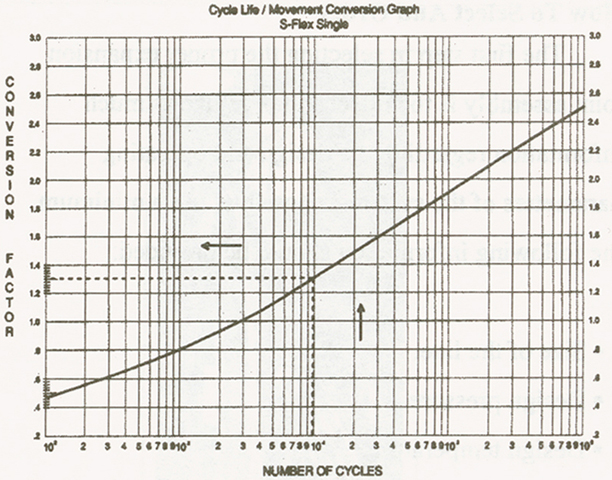
How To Use Graph
Example: Enter graph at 1,000 cycles; read C. F. of 1.
|
|
CYCLE LIFE AND RATED MOVEMENT- UNIVERSAL PIPE EXPANSION JOINTS PT&P’s universal pipe expansion joints are designed for 3000 cycles for any one tabulated movement shown. Cycle life may be increased, or movement may be increased (decreasing the cycle life) by utilizing the graph shown on this page. The graph may also be used for superimposing more than one movement condition on the bellows at one time. It is important to remember that the movements shown in the bellows data pages do not allow for any installation misalignment. A proper specification for a bellows pipe expansion joint should reflect what the actual system movements will be. To ensure the highest quality bellows for the least cost, all movement conditions must be taken into account. Examples of movement conditions that typically occur in a piping system are:
|
|
 |
|
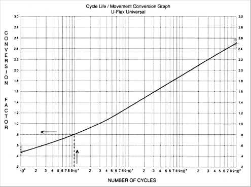
How to Use Graph
Example: Enter graph at 1,000 cycles; read C. F. of 0.80 Note: Maximum increase in movements for combined movement conditions shall not exceed 110% of catalog rated movement Note: Please reference the print version of the U.S. Bellows, Inc. Expansion Joint Catalog for reference tables containing technical data on Expansion Joints. |
|
|
Cycle Life and Rated Movement: Externally Pressurized Pipe Expansion Joint |
|||||||
|
Typical movement conditions that occur in a piping system are:
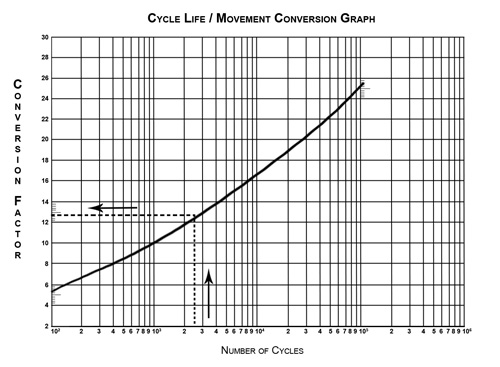
U.S. Bellows externally pressurized pipe expansion joints are designed for 1000 cycles for any one tabulated movement shown. The movement may be increased, decreasing the cycle life, by using the graph below. This graph may also be used for superimposing more than one movement condition on the bellows at one time. |
|||||||
 |
|||||||
Using the graph: example: 2500 cycles reads C.F. of 1.23
|
|||||||
|
Note: Maximum increase in movements for combined movement conditions shall not exceed 130% of catalog rated movements. Note: Please reference the print version of the U.S. Bellows, Inc. Expansion Joint Catalog for reference tables containing technical data on Externally Pressurized Expansion Joints
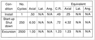
EXAMPLE 1. Assume the following pipe expansion joint design criteria:
2. Turn to the Conversion Factor Graph, and calculate equivalent catalog movements.
Total = 5.80 3. Refer to page 93, 12-inch nominal diameter single externally pressurized pipe expansion joints, and go to the lowest pressure rating that is equal to or greater than specified design pressure (125 psig) which will be the 150 psig rated pipe expansion joints. Compare the total equivalent catalog movements to those shown in the catalog, keeping in mind that the tabulated movements shown in the catalog are for 1,000 cycles for one movement only.4. Select the appropriate pipe expansion joint that meets the movement criteria. Since the total equivalent axial movement is 5.80-inches, the unit that is rated for eight inches is the correct selection.5. Include the designations for the type (XS for XFlex/single), drain connection (D), and purge connection (P). 6. The resulting PT&P part number would then be as follows:
|
|||||||