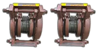
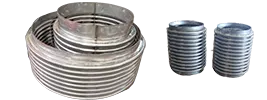
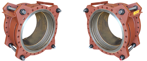
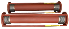
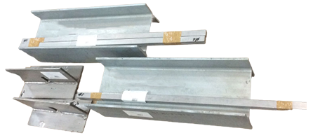
The single pipe expansion joint is simply a bellows element with end connections. Regardless of accessories, it will deflect in any direction or plane that the bellows will. It requires that the piping be controlled as to the direction of the movements required of the unit. The pipe expansion joint should not be expected to control the movement of the pipe, and will not resist any deflections with any force other than the resistance of the bellows.
This pipe expansion joint is simply a bellows element with end connections. Regardless of accessories, such as liners and covers, it will deflect in any direction or plane that the bellows will. It is the least expensive type but requires that the piping be controlled as to the direction of the movements required of the unit. The pipe expansion joint should not be expected to control the movement of the pipe. If the piping analysis shows that the pipe expansion joint must accept axial compression, then the piping must be guided and constrained so that only that movement will occur. This expansion joint will not resist any deflections with any force other than the resistance of the bellows, which is a function of the spring rate times the deflection amount. It is incapable of resisting the pressure thrust along its axis, which is the product of the pressure times the effective, or cross-sectional, area of the bellows. Large diameter units, even with low pressures, can generate very large axial pressure thrust forces, which must be reacted by main and directional anchors. Otherwise, the expansion joint will extend with disastrous results.
Rated life cycle at 650°F is 3000 cycles for any one tabulated movement.
To combine axial, lateral and angular movements, please refer to the…how to order section
To increase cycle life or movements, please refer to the graph on…cycle life
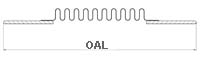
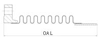
Rated bellows extension is equal to rated axial movement. Provided bellows is precompressed the amount of design extension. Installed overall length will decrease by the amount of precompression.
Maximum test pressure: 1.5 X rated working pressure.
Bellows rated for 650°F: For appropriate flange temperature/pressure ratings, see…catalog flange data
Torsional spring rate data provided only for modeling expansion joints on computer stress programs. Please consult factory for allowable torsional loadings.
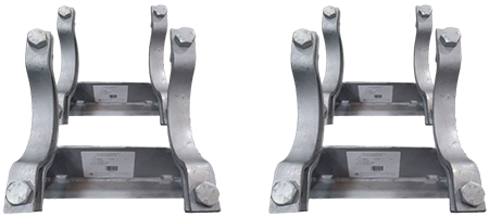
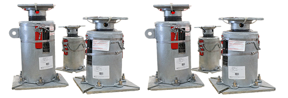
Overall lengths and weights for unrestrained expansion joints only. Consult factory for information regarding tied, hinged, or gimbal expansion joints.
Pressure thrust load applied to adjacent pipe anchors/equipment when unrestrained expansion joints are used.
Dia.
Pressure
Overall Length and Weight
Non-concurrent movements
Spring Rates
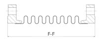
Flanged Ends
Weld Ends
Combination Ends
Axial
Lateral
Angular
Axial
Lateral
Angular
Torsional
Overall Length
Weight
Overall Length
Weight
Overall Length
Weight
Comp-ression
PSIG
in.
lb
in.
lb
in.
lb
in.
in.
deg.
lb./in.
lb./in.
in.
in./lb./deg. x 106
kg/cm2
mm
kg
mm
kg
mm
kg
mm
mm
Grad
kg/mm
kg/mm
N-M/Grad
N-M/Grad x 105
3
170
6
7
12
6
9
7
0.92
0.28
10
304
560
11
0.0087
11.9
152
3.18
305
2.73
229
3.18
23.4
7.11
11
5
10
1.1
0.0088
90
9
7
15
7
12
7
1.87
1.03
10
169
93
6
0.0048
6.3
229
3.18
381
3.18
305
3.18
47.5
26.2
11
3
2
0.6
0.0049
40
12
8
18
7
15
8
2.84
2.27
10
117
31
4
0.0033
2.8
305
3.64
457
3.18
381
3.64
72.1
57.7
11
2
1
0.4
0.0034
3
500
6
27
12
6
9
17
0.36
0.08
10
2020
7142
72
0.0214
35.1
152
12.3
305
2.73
229
7.73
9.14
2.03
11
36
128
7.3
0.0217
500
9
28
15
7
12
18
0.77
0.36
10
943
726
33
0.01
35.1
229
12.7
381
3.18
305
8.18
19.6
9.14
11
17
13
3.4
0.0101
250
12
29
18
8
15
19
1.3
0.93
10
615
201
22
0.0065
17.6
305
13.2
457
3.64
381
8.64
33
23.6
11
11
4
2.2
0.0066
Materials Bellows: A240-T304. Alternate materials available upon request. Refer to the… materials section Flanges: ASTM A105.
40-170 PSIG Series: 150 lb. ANSI B16.5 RFSO.
250-500 PSIG Series: 300 lb. ANSI B16.5 RFSO
Plate flanges and angle flanges available for low-pressure systems. Pipe: ASTM A53/A106.
40-70 PSIG Series: Std. Wt. Pipe.
250-500 PSIG Series: Std. Wt. Pipe Liners: A240-T304. Covers: Carbon steel. Tie Rods, Hinges, Gimbals: Carbon steel
Rated life cycle at 650°F is 3000 cycles for any one tabulated movement.
To combine axial, lateral and angular movements, please refer to the… how to order section
To increase cycle life or movements, please refer to graph on… cycle life
Rated bellows extension is equal to rated axial movement. Provided bellows is precompressed the amount of design extension. Installed overall length will decrease by the amount of precompression.
Maximum test pressure: 1.5 X rated working pressure.
Bellows rated for 650°F: For appropriate flange temperature/pressure ratings, see… catalog flange data
Torsional spring rate data provided only for modeling expansion joints on computer stress programs. Please consult factory for allowable torsional loadings.
Overall lengths and weights for unrestrained expansion joints only. Consult factory for information regarding tied, hinged, or gimbal expansion joints.
Pressure thrust load applied to adjacent pipe anchors/equipment when unrestrained expansion joints are used.
Dia
Pressure
Overall Length and Weight
Non-concurrent movements
Spring rates
Flanged Ends
Weld Ends
Combination Ends
Axial
Lateral
Angular
Axial
Lateral
Angular
Torsional
Overall Length
Weight
Overall Length
Weight
Overall Length
Weight
Compression
PSIG
in.
lb.
in.
lb.
in.
lb.
in.
in.
deg.
lb./in.
lb./in.
in.
in./lb./deg. x 106
kg/cm 2
mm
kg
mm
kg
mm
kg
mm
mm
Grad
kg/mm
kg/mm
N-M/Grad
N-M/Grad x 105
3.5
170
6
23
12
8
9
15
0.9
0.23
10
349
873
16
0.013
11.9
152
10.5
305
3.64
229
6.82
22.9
5.84
11
6
16
1.6
0.0132
100
9
24
15
8
12
16
1.75
0.84
10
194
141
9
0.0072
7
229
10.9
381
3.64
305
7.27
44.5
21.3
11
3
3
0.9
0.0073
40
12
24
18
9
15
17
2.69
1.89
10
134
46
6
0.0049
2.8
305
10.9
457
4.09
381
7.73
68.3
48
11
2
1
0.6
0.005
3.5
500
6
35
12
8
9
21
0.32
0.06
8
2710
13345
121
0.0361
35.1
152
15.9
305
3.64
229
9.55
8.13
1.52
9
48
239
12.3
0.0367
500
9
36
15
9
12
22
0.72
0.29
10
1161
1182
52
0.0157
35.1
229
16.4
381
4.09
305
10
18.3
7.37
11
21
21
5.3
0.016
300
12
37
18
10
15
23
1.23
0.77
10
739
315
33
0.01
21.1
305
16.8
457
4.55
381
10.5
31.2
19.6
11
13
6
3.4
0.0102
Materials Bellows: A240-T304. Alternate materials available upon request. Refer to the… materials section. Flanges: ASTM A105.
40-170 PSIG Series: 150 lb. ANSI B16.5 RFSO.
300-500 PSIG Series: 300 lb. ANSI B16.5 RFSO
Plate flanges and angle flanges available for low-pressure systems. Pipe: ASTM A53/A106.
40-70 PSIG Series: Std. Wt. Pipe.
300-500 PSIG Series: Std. Wt. Pipe Liners: A240-T304. Covers: Carbon steel. Tie Rods, Hinges, Gimbals: Carbon steel
Rated life cycle at 650°F is 3000 cycles for any one tabulated movement.
To combine axial, lateral and angular movements, please refer to the… how to order section
To increase cycle life or movements, please refer to graph on… cycle life
Rated bellows extension is equal to rated axial movement. Provided bellows is precompressed the amount of design extension. Installed overall length will decrease by the amount of precompression.
Maximum test pressure: 1.5 X rated working pressure.
Bellows rated for 650°F: For appropriate flange temperature/pressure ratings, see… catalog flange data
Torsional spring rate data provided only for modeling expansion joints on computer stress programs. Please consult factory for allowable torsional loadings.
Overall lengths and weights for unrestrained expansion joints only. Consult factory for information regarding tied, hinged, or gimbal expansion joints.
Pressure thrust load applied to adjacent pipe anchors/equipment when unrestrained expansion joints are used.
Dia
Pressure
Overall Length and Weight
Non-concurrant movements
Spring rates
Flanged Ends
Weld Ends
Combination Ends
Axial
Lateral
Angular
Axial
Lateral
Angular
Torsional
Overall Length
Weight
Overall Length
Weight
Overall Length
Weight
Compression
PSIG
in.
lb.
in.
lb.
in.
lb.
in.
in.
deg.
lb./in.
lb./in.
in.
in./lb./deg. x 106
kg/cm 2
mm
kg
mm
kg
mm
kg
mm
mm
Grad
kg/mm
kg/mm
N-M/Grad
N-M/Grad x 105
4
100
6
27
12
9
9
18
1.23
0.27
10
222
774
13
0.0168
7
152
12.3
305
4.09
229
818
31.2
6.96
11
4
14
1.3
0.017
65
9
28
15
10
12
19
2.49
1.03
10
118
115
7
0.0089
4.6
229
12.7
381
4.55
305
8.64
63.2
26.2
11
2
2
0.7
0.009
30
12
29
18
11
15
20
3.89
2.36
10
80
36
5
0.006
2.1
305
13.2
457
5
381
9.09
98.8
59.9
11
1
1
0.5
0.0061
4
275
6
45
10
9
8
27
0.46
0.07
10
1549
12199
90
0.0433
19.3
152
20.5
254
4.09
203
12.3
11.7
1.78
11
28
218
9.2
0.0441
275
9
47
13
11
11
29
1.07
0.36
10
664
960
38
0.0186
19.3
229
21.4
330
5
279
13.2
27.2
9.14
11
12
17
3.9
0.0189
175
12
48
16
12
14
30
1.81
0.96
10
423
247
24
0.0118
12.3
305
21.8
406
5.45
356
13.6
46
24.4
11
8
4
2.4
0.012
Materials Bellows: A240-T304. Alternate materials available upon request. Refer to the… materials section Flanges: ASTM A105.
30-100 PSIG Series: 150 lb. ANSI B16.5 RFSO.
175-275 PSIG Series: 300 lb. ANSI B16.5 RFSO
Plate flanges and angle flanges available for low-pressure systems. Pipe: ASTM A53/A106.
30-100 PSIG Series: Std. Wt. Pipe.
175-275 PSIG Series: Std. Wt. Pipe Liners: A240-T304. Covers: Carbon steel. Tie Rods, Hinges, Gimbals: Carbon steel
Rated life cycle at 650°F is 3000 cycles for any one tabulated movement.
To combine axial, lateral and angular movements, please refer to the… how to order section
To increase cycle life or movements, please refer to graph on… cycle life
Rated bellows extension is equal to rated axial movement. Provided bellows is precompressed the amount of design extension. Installed overall length will decrease by the amount of precompression.
Maximum test pressure: 1.5 X rated working pressure.
Bellows rated for 650°F: For appropriate flange temperature/pressure ratings, see… catalog flange data
Torsional spring rate data provided only for modeling expansion joints on computer stress programs. Please consult factory for allowable torsional loadings.
Overall lengths and weights for unrestrained expansion joints only. Consult factory for information regarding tied, hinged, or gimbal expansion joints.
Pressure thrust load applied to adjacent pipe anchors/equipment when unrestrained expansion joints are used.
Dia
Pressure
Overall Length and Weight
Non-concurrant movements
Spring rates
Flanged Ends
Weld Ends
Combination Ends
Axial
Lateral
Angular
Axial
Lateral
Angular
Torsional
Overall Length
Weight
Overall Length
Weight
Overall Length
Weight
Compression
PSIG
in.
lb.
in.
lb.
in.
lb.
in.
in.
deg.
lb./in.
lb./in.
in.
in./lb./deg. x 106
kg/cm 2
mm
kg
mm
kg
mm
kg
mm
mm
Grad
kg/mm
kg/mm
N-M/Grad
N-M/Grad x 105
5
100
6
31
12
12
9
22
1.17
0.2
10
277
1641
23
0.0319
7
152
14.1
305
5.45
229
10
29.7
5.08
11
5
29
2.3
0.0325
85
9
32
15
13
12
23
2.28
0.75
10
147
226
12
0.0168
6
229
14.5
381
5.91
305
10.5
57.9
19.1
11
3
4
1.2
0.0171
35
12
34
18
14
15
24
3.76
1.85
10
100
69
8
0.0114
2.5
305
15.5
457
6.36
381
10.9
95.5
47
11
2
1
0.8
0.116
5
275
6
57
10
12
8
35
0.39
0.04
7
2320
33633
196
0.0963
19.3
152
25.9
254
5.45
203
15.9
9.91
1.02
8
42
602
19.9
0.098
275
9
59
13
14
11
36
1.01
0.27
10
892
2070
75
0.0373
19.3
229
26.8
330
6.36
279
16.4
25.4
6.86
11
16
37
7.6
0.038
235
12
61
16
15
14
38
1.66
0.71
10
552
500
47
0.0232
16.5
305
27.7
406
6.82
356
17.3
42.2
18
11
10
9
4.8
0.0235
Materials Bellows: A240-T304. Alternate materials available upon request. Refer to the… materials section Flanges: ASTM A105.
35-100 PSIG Series: 150 lb. ANSI B16.5 RFSO.
235-275 PSIG Series: 300 lb. ANSI B16.5 RFSO
Plate flanges and angle flanges available for low-pressure systems. Pipe: ASTM A53/A106.
35-100 PSIG Series: Std. Wt. Pipe.
235-275 PSIG Series: Std. Wt. Pipe Liners: A240-T304. Covers: Carbon steel. Tie Rods, Hinges, Gimbals: Carbon steel
Rated life cycle at 650°F is 3000 cycles for any one tabulated movement.
To combine axial, lateral and angular movements, please refer to the how to order section.
To increase cycle life or movements, please refer to graph on cycle life.
Rated bellows extension is equal to rated axial movement. Provided bellows is precompressed the amount of design extension. Installed overall length will decrease by the amount of precompression.
Maximum test pressure: 1.5 X rated working pressure.
Bellows rated for 650°F: See catalog flange data for appropriate flange temperature/pressure ratings.
Torsional spring rate data provided only for modeling expansion joints on computer stress programs. Please consult factory for allowable torsional loadings.
Overall lengths and weights for unrestrained expansion joints only. Consult factory for information regarding tied, hinged, or gimbal expansion joints.
Pressure thrust load applied to adjacent pipe anchors/equipment when unrestrained expansion joints are used.
Diameter
Pressure
Overall Length and Weight
Non-concurrant
movements
Spring rates
Flanged
Ends
Weld
Ends
Combination
Ends
Axial
Lateral
Angular
Axial
Lateral
Angular
Torsional
Overall Length
Weight
Overall Length
Weight
Overall Length
Weight
Compression
PSIG
in.
lb.
in.
lb.
in.
lb.
in.
in.
deg.
lb./in.
lb./in.
in./lb./deg.
in./lb./deg.
x 106
kg/cm 2
mm
kg
mm
kg
mm
kg
mm
mm
Grad
kg/mm
kg/mm
N-M/Grad
N-M/Grad
x 105
10
100
12
94
16
37
14
66
2.74
0.62
10
427
1374
132
0.1975
7
305
42.7
406
16.8
356
30
69.6
15.7
11
8
25
13.4
0.2009
60
18
99
22
43
20
71
5.08
2.01
10
256
273
79
0.1174
4.2
457
45
559
19.5
508
32.3
129
51.1
11
5
5
8
0.1194
30
24
104
28
48
26
76
7.58
4.27
10
183
96
57
0.0835
2.1
610
47.3
711
21.8
660
34.5
193
108
11
3
2
5.8
0.0849
10
275
12
172
15
40
14
106
1.23
0.23
10
2254
10547
699
0.41
19.3
305
78.2
381
18.2
356
48.2
31.2
5.84
11
40
189
71.1
0.417
275
18
180
21
48
20
114
2.3
0.82
10
1214
1592
376
0.2199
19.3
457
81.8
533
21.8
508
51.8
58.4
20.8
11
22
28
38.2
0.2236
325
24
213
27
80
26
147
3.4
1.78
10
1673
1023
523
0.1604
22.8
610
96.8
686
36.4
660
66.8
86.4
45.2
11
30
18
53.2
0.1631
Materials Bellows: A240-T304. Alternate materials available upon request. Refer to the materials section. Flanges: ASTM A105.
30-100 PSIG Series: 150 lb. ANSI B16.5 RFSO.
275-325 PSIG Series: 300 lb. ANSI B16.5 RFSO
Plate flanges and angle flanges available for low pressure systems. Pipe: ASTM A53/A106.
30-100 PSIG Series: Std. Wt. Pipe.
275-325 PSIG Series: Std. Wt. Pipe. Liners: A240-T304. Covers: Carbon steel. Tie Rods, Hinges, Gimbals: Carbon steel
Rated life cycle at 650°F is 3000 cycles for any one tabulated movement.
To combine axial, lateral and angular movements, please refer to the how to order section.
To increase cycle life or movements, please refer to graph on cycle life.
Rated bellows extension is equal to rated axial movement. Provided bellows is precompressed the amount of design extension. Installed overall length will decrease by the amount of precompression.
Maximum test pressure: 1.5 X rated working pressure.
Bellows rated for 650°F: See catalog flange data for appropriate flange temperature/pressure ratings.
Torsional spring rate data provided only for modeling expansion joints on computer stress programs. Please consult factory for allowable torsional loadings.
Overall lengths and weights for unrestrained expansion joints only. Consult factory for information regarding tied, hinged, or gimbal expansion joints.
Pressure thrust load applied to adjacent pipe anchors/equipment when unrestrained expansion joints are used.
Diameter
Pressure
Overall Length and Weight
Non-concurrant
movements
Spring rates
Flanged
Ends
Weld
Ends
Combination
Ends
Axial
Axial
Lateral
Angular
Torsional
Overall Length
Weight
Overall Length
Weight
Overall Length
Weight
Compression
PSIG
in.
lb.
in.
lb.
in.
lb.
in.
in.
deg.
lb./in.
lb./in.
n./lb./deg.
in./lb./deg.
x 106
kg/cm2
mm
kg
mm
kg
mm
kg
mm
mm
Grad
kg/mm
kg/mm
N-M/Grad
N-M/Grad
x 105
12
80
12
137
16
45
14
91
2.94
0.53
10
416
2113
179
0.3358
5.6
305
62.3
406
20.5
356
41.4
74.7
13.5
11
7
38
18.2
0.3415
60
18
144
22
52
20
98
5.41
1.75
10
238
378
102
0.191
4.2
457
65.5
559
23.6
508
44.5
137
44.5
11
4
7
10.4
0.1943
25
24
151
28
58
26
104
8.57
4
10
166
128
7.1
0.1335
1.8
610
68.6
711
26.4
660
47.3
218
102
11
3
2
7.2
0.1357
12
210
12
243
16
49
14
146
1.41
0.21
10
1952
14794
840
0.6363
14.8
305
110
406
22.3
356
66.4
35.8
5.33
11
35
265
85.4
0.6471
210
18
253
22
59
20
156
2.68
0.78
10
1051
2074
453
0.3387
14.8
457
115
559
26.8
508
70.9
68.1
19.8
11
19
37
46.1
0.3445
300
24
296
28
101
26
198
3.97
1.71
10
1447
1295
627
0.2447
21.1
610
135
711
45.9
660
90
101
43.3
11
26
23
63.8
0.2488
Bellows: A240-T304. Alternate materials available upon request. Refer to the materials section. Flanges: ASTM A105.
25-80 PSIG Series: 150 lb. ANSI B16.5 RFSO.
210-300 PSIG Series: 300 lb. ANSI B16.5 RFSO
Plate flanges and angle flanges available for low pressure systems. Pipe: ASTM A53/A106.
25-80 PSIG Series: Std. Wt. Pipe.
210-300 PSIG Series: Std. Wt. Pipe. Liners: A240-T304. Covers: Carbon steel. Tie Rods, Hinges, Gimbals: Carbon steel
Rated life cycle at 650°F is 3000 cycles for any one tabulated movement.
To combine axial, lateral and angular movements, please refer to the how to order section.
To increase cycle life or movements, please refer to graph on cycle life.
Rated bellows extension is equal to rated axial movement. Provided bellows is precompressed the amount of design extension. Installed overall length will decrease by the amount of precompression.
Maximum test pressure: 1.5 X rated working pressure.
Bellows rated for 650°F: See catalog flange data for appropriate flange temperature/pressure ratings.
Torsional spring rate data provided only for modeling expansion joints on computer stress programs. Please consult factory for allowable torsional loadings.
Overall lengths and weights for unrestrained expansion joints only. Consult factory for information regarding tied, hinged, or gimbal expansion joints.
Pressure thrust load applied to adjacent pipe anchors/equipment when unrestrained expansion joints are used.
Diameter
Pressure
Overall Length and Weight
Non-concurrant
movements
Spring rates
Flanged
Ends
Weld
Ends
Combination
Ends
Axial
Axial
Lateral
Angular
Torsional
Overall Length
Weight
Overall Length
Weight
Overall Length
Weight
Compression
PSIG
in.
lb.
in.
lb.
in.
lb.
in.
in.
deg.
lb./in.
lb./in.
n./lb./deg.
in./lb./deg.
x 106
kg/cm2
mm
kg
mm
kg
mm
kg
mm
mm
Grad
kg/mm
kg/mm
N-M/Grad
N-M/Grad
x 105
14
80
12
190
16
50
14
120
2.9
0.49
10
459
2639
234
0.4418
5.6
305
86.4
406
22.7
356
54.5
73.7
12.4
11
8
47
23.8
0.4493
65
18
198
22
57
20
127
5.27
1.55
10
262
503
133
0.2531
4.6
457
90
559
25.9
508
57.7
134
39.4
11
5
9
13.5
0.2574
30
24
205
28
64
26
134
8.14
3.46
10
183
169
93
0.1767
2.1
610
93.2
711
29.1
660
60.9
207
87.9
11
3
3
9.5
0.1797
14
225
12
393
16
52
14
222
1.25
0.16
10
2509
24470
1281
0.9569
15.8
305
179
406
23.6
356
101
31.8
4.06
11
45
438
130.3
0.9731
225
18
404
22
64
20
234
2.5
0.65
10
1255
3059
641
0.4784
15.8
457
184
559
29.1
508
106
63.5
16.5
11
22
55
65.2
0.4866
350
24
449
28
108
26
279
3.72
1.46
10
1682
1834
864
0.3374
24.6
610
204
711
49.1
660
127
94.5
37.1
11
30
33
87.9
0.3431
Materials Bellows: A240-T304. Alternate materials available upon request. Refer to the materials section. Flanges: ASTM A105.
30-80 PSIG Series: 150 lb. ANSI B16.5 RFSO.
225-350 PSIG Series: 300 lb. ANSI B16.5 RFSO
Plate flanges and angle flanges available for low pressure systems. Pipe: ASTM A53/A106.
30-80 PSIG Series: Std. Wt. Pipe.
225-350 PSIG Series: Std. Wt. Pipe. Liners: A240-T304. Covers: Carbon steel. Tie Rods, Hinges, Gimbals: Carbon steel
Rated life cycle at 650°F is 3000 cycles for any one tabulated movement.
To combine axial, lateral and angular movements, please refer to the how to order section.
To increase cycle life or movements, please refer to graph on cycle life.
Rated bellows extension is equal to rated axial movement. Provided bellows is precompressed the amount of design extension. Installed overall length will decrease by the amount of precompression.
Maximum test pressure: 1.5 X rated working pressure.
Bellows rated for 650°F: See catalog flange data for appropriate flange temperature/pressure ratings.
Torsional spring rate data provided only for modeling expansion joints on computer stress programs. Please consult factory for allowable torsional loadings.
Overall lengths and weights for unrestrained expansion joints only. Consult factory for information regarding tied, hinged, or gimbal expansion joints.
Pressure thrust load applied to adjacent pipe anchors/equipment when unrestrained expansion joints are used.
Dia
Pressure
Overall Length and Weight
Non-concurrant
movements
Spring rates
Flanged
Ends
Weld
Ends
Combination
Ends
Axial
Lateral
Angular
Axial
Lateral
Angular
Torsional
Overall Length
Weight
Overall Length
Weight
Overall Length
Weight
Compression
PSIG
in.
lb.
in.
lb.
in.
lb.
in.
in.
deg.
lb./in.
lb./in.
in./lb./deg.
in./lb./deg.
x 106
kg/cm 2
mm
kg
mm
kg
mm
kg
mm
mm
Grad
kg/mm
kg/mm
N-M/Grad
N-M/Grad
x 105
22
60
12
171
17
82
15
127
3.64
0.44
10
487
5534
582
1.4134
4.2
305
77.7
432
37.3
381
57.7
92.5
11.2
11
9
99
59.2
1.4374
60
18
184
23
94
21
139
6.07
1.25
10
292
1141
349
0.8441
4.2
457
83.6
584
42.7
533
63.2
154
31.8
11
5
20
35.5
0.8584
30
24
196
29
107
27
151
9.48
2.77
10
209
408
249
0.6017
2.1
610
89.1
737
48.6
686
68.6
2.41
70.4
11
4
7
25.3
0.6119
22
165
12
391
14
84
13
237
1.45
0.12
7
2994
74513
3583
3.4407
11.6
305
178
356
38.2
330
108
36.8
3.05
8
54
1333
364.4
3.4992
165
18
411
20
103
19
257
2.41
0.49
10
1497
8922
1792
1.7127
11.6
457
187
508
46.8
483
117
73.9
12.4
11
27
160
182.2
1.7419
165
24
430
26
123
25
276
4.36
1.1
10
998
2606
1194
1.1401
11.6
610
195
660
55.9
635
125
111
27.9
11
18
47
121.4
1.1595
22
350
12
769
12
112
12
441
0.92
0.05
5
9012
465407
10831
5.3572
24.6
305
350
305
50.9
305
200
23.4
1.27
5
161
8329
1101.5
5.4483
350
18
807
18
150
18
478
2.3
0.33
10
3605
29786
4332
2.1429
24.6
457
367
457
68.2
457
217
58.4
8.38
11
65
533
440.6
2.1793
350
24
844
24
187
24
516
3.69
0.84
10
2253
7272
2708
1.3393
24.6
610
384
610
85
610
235
93.7
21.3
11
40
130
275.4
1.3621
Materials Bellows: A240-T304. Alternate materials available upon request. Refer to the materials section. Flanges: ASTM A105.
30-60 PSIG Series: 125 lb. Lt. Wt. FFSO
165 PSIG Series: 150 lb. ANSI B16.5 RFSO
350 PSIG Series: 300 lb. ANSI B16.5 RFSO
Plate flanges and angle flanges available for low pressure systems. Pipe: ASTM A53/A106/285-C.
30-60 PSIG Series: 0.375-inch Wall
165 PSIG Series: 0.375-inch wall.
350 PSIG Series: 0.500-inch wall. Liners: A240-T304. Covers: Carbon steel. Tie Rods, Hinges, Gimbals: Carbon steel
Rated life cycle at 650°F is 3000 cycles for any one tabulated movement.
To combine axial, lateral and angular movements, please refer to the how to order section.
To increase cycle life or movements, please refer to graph on cycle life.
Rated bellows extension is equal to rated axial movement. Provided bellows is precompressed the amount of design extension. Installed overall length will decrease by the amount of precompression.
Maximum test pressure: 1.5 X rated working pressure.
Bellows rated for 650°F: See catalog flange data for appropriate flange temperature/pressure ratings.
Torsional spring rate data provided only for modeling expansion joints on computer stress programs. Please consult factory for allowable torsional loadings.
Overall lengths and weights for unrestrained expansion joints only. Consult factory for information regarding tied, hinged, or gimbal expansion joints.
Pressure thrust load applied to adjacent pipe anchors/equipment when unrestrained expansion joints are used.
Dia
Pressure
Overall Length and Weight
Non-concurrant
movements
Spring rates
Flanged
Ends
Weld
Ends
Combination
Ends
Axial
Lateral
Angular
Axial
Lateral
Angular
Torsional
Overall Length
Weight
Overall Length
Weight
Overall Length
Weight
Compression
PSIG
in.
lb.
in.
lb.
in.
lb.
in.
in.
deg.
lb./in.
lb./in.
in./lb./deg.
in./lb./deg.
x 106
kg/cm 2
mm
kg
mm
kg
mm
kg
mm
mm
Grad
kg/mm
kg/mm
N-M/Grad
N-M/Grad
x 105
26
60
12
273
16
97
14
185
3.57
0.37
10
577
9005
946
2.3301
4.2
305
124
406
44.1
356
84.1
90.7
9.4
11
10
161
96.2
2.3697
60
18
287
22
112
20
200
5.99
1.06
10
346
1857
568
1.3915
4.2
457
130
559
50.9
508
90.9
152
26.9
11
6
33
57.8
1.4152
40
24
302
28
126
26
214
9.11
2.27
10
247
663
406
0.9919
2.8
610
137
711
57.3
660
97.3
231
57.7
11
4
12
41.3
1.0088
26
165
Customer to specify flange configuration. Weights and O.A.L. will be furnished upon receipt of this information.
16
107
Customer to specify flange configuration. Weights and O.A.L. will be furnished upon receipt of this information.
1.93
0.19
8
2664
46954
4371
4.2135
11.6
406
48.6
49
4.83
9
48
840
444.5
4.2852
165
22
130
3.37
0.57
10
1522
8761
2498
2.4077
11.6
559
59.1
85.6
14.5
11
27
157
254
2.4487
165
28
153
4.82
1.17
10
1066
3005
1748
1.6854
11.6
711
69.5
122
29.7
11
19
54
177.8
1.7141
26
335
16
162
1.84
0.18
8
5343
94509
8797
4.4038
23.5
406
73.6
46.7
4.57
9
96
1691
894.7
4.4786
335
22
207
3.21
0.55
10
3053
17634
5027
2.5164
23.5
559
94.1
81.5
14
11
55
316
511.2
2.5592
335
28
251
4.59
1.11
10
2137
6049
3519
1.7615
23.5
711
114
117
28.2
11
38
108
357.9
1.7915
Materials Bellows: A240-T304. Alternate materials available upon request. Refer to the materials section. Flanges: ASTM A105.
40-60 PSIG Series: 125 lb. Lt. Wt. FFSO.
For 165 psig and 335 psig Series: Customer to specify actual flanges required.
Plate flanges and angle flanges available for low pressure systems. Pipe: ASTM A53/A106.
40-60 PSIG Series: 0.375-inch wall.
165 PSIG Series: 0.375-inch wall.
335 PSIG Series: 0.500-inch wall. Liners: A240-T304. Covers: Carbon steel. Tie Rods, Hinges, Gimbals: Carbon steel
Rated life cycle at 650°F is 3000 cycles for any one tabulated movement.
To combine axial, lateral and angular movements, please refer to the how to order section.
To increase cycle life or movements, please refer to graph on cycle life.
Rated bellows extension is equal to rated axial movement. Provided bellows is precompressed the amount of design extension. Installed overall length will decrease by the amount of precompression.
Maximum test pressure: 1.5 X rated working pressure.
Bellows rated for 650°F: See catalog flange data for appropriate flange temperature/pressure ratings.
Torsional spring rate data provided only for modeling expansion joints on computer stress programs. Please consult factory for allowable torsional loadings.
Overall lengths and weights for unrestrained expansion joints only. Consult factory for information regarding tied, hinged, or gimbal expansion joints.
Pressure thrust load applied to adjacent pipe anchors/equipment when unrestrained expansion joints are used.
Dia
Pressure
Overall Length and Weight
Non-concurrant
movements
Spring rates
Flanged
Ends
Weld
Ends
Combination
Ends
Axial
Lateral
Angular
Axial
Lateral
Angular
Torsional
Overall Length
Weight
Overall Length
Weight
Overall Length
Weight
Compression
PSIG
in.
lb.
in.
lb.
in.
lb.
in.
in.
deg.
lb./in.
lb./in.
in./lb./deg.
in./lb./deg.
x 106
kg/cm 2
mm
kg
mm
kg
mm
kg
mm
mm
Grad
kg/mm
kg/mm
N-M/Grad
N-M/Grad
x 105
28
60
12
305
16
105
14
205
3.57
0.34
10
623
11183
1175
2.9088
4.2
305
139
406
47.7
356
93.2
90.7
8.64
11
11
200
119.5
2.9582
60
18
320
22
120
20
220
5.95
0.98
10
374
2306
705
1.7371
4.2
457
145
559
54.5
508
100
151
24.9
11
7
41
71.7
1.7666
40
24
336
28
136
26
236
9.04
2.1
10
267
824
504
1.2383
2.8
610
153
711
61.8
660
107
230
53.3
11
5
15
51.3
1.2594
28
16
Customer to specify flange configuration. Weights and O.A.L. will be furnished upon receipt of this information.
16
116
Customer to specify flange configuration. Weights and O.A.L. will be furnished upon receipt of this information.
1.92
0.17
8
2873
58303
5427
5.2585
11.2
406
52.7
48.8
4.32
8
51
1043
551.9
5.3479
160
22
140
3.37
0.53
10
1642
10879
3101
3.0048
11.2
559
63.6
85.6
13.5
11
29
195
315.4
3.0559
160
28
165
4.81
1.09
10
1149
3731
2171
2.1034
11.2
711
75
122
27.7
11
21
67
220.8
2.1391
28
315
16
175
1.81
0.16
7
5762
117299
10919
5.4916
22.1
406
79.5
46
4.06
8
103
2099
1110.5
5.5849
315
22
223
3.25
0.51
10
3293
21887
6239
3.138
22.1
559
101
82.6
13
11
59
392
634.5
3.1914
315
28
271
4.64
1.05
10
2305
7507
4367
2.1966
22.1
711
123
118
26.7
11
41
134
444.1
2.234
Materials Bellows: A240-T304. Alternate materials available upon request. Refer to the materials section. Flanges: ASTM A105.
40-60 PSIG Series: 125 lb Lt. Wt. FFSO.
For 160 psig and 315 psig Series: Customer to specify actual flanges required.
Plate flanges and angle flanges available for low pressure systems. Pipe: ASTM A285-C.
40-60 PSIG Series: 0.375-inch wall.
165 PSIG Series: 0.375-inch wall.
315 PSIG Series: 0.500-inch wall. Liners: A240-T304. Covers: Carbon steel. Tie Rods, Hinges, Gimbals: Carbon steel
Rated life cycle at 650°F is 3000 cycles for any one tabulated movement.
To combine axial, lateral and angular movements, please refer to the how to order section.
To increase cycle life or movements, please refer to graph on cycle life.
Rated bellows extension is equal to rated axial movement. Provided bellows is precompressed the amount of design extension. Installed overall length will decrease by the amount of precompression.
Maximum test pressure: 1.5 X rated working pressure.
Bellows rated for 650°F: See catalog flange data for appropriate flange temperature/pressure ratings.
Torsional spring rate data provided only for modeling expansion joints on computer stress programs. Please consult factory for allowable torsional loadings.
Overall lengths and weights for unrestrained expansion joints only. Consult factory for information regarding tied, hinged, or gimbal expansion joints.
Pressure thrust load applied to adjacent pipe anchors/equipment when unrestrained expansion joints are used.
Dia
Pressure
Overall Length and Weight
Non-concurrant
movements
Spring rates
Flanged
Ends
Weld
Ends
Combination
Ends
Axial
Lateral
Angular
Axial
Lateral
Angular
Torsional
Overall Length
Weight
Overall Length
Weight
Overall Length
Weight
Compression
PSIG
in.
lb.
in.
lb.
in.
lb.
in.
in.
deg.
lb./in.
lb./in.
in./lb./deg.
in./lb./deg.
x 106
kg/cm 2
mm
kg
mm
kg
mm
kg
mm
mm
Grad
kg/mm
kg/mm
N-M/Grad
N-M/Grad
x 105
30
50
12
328
16
114
14
221
3.98
0.36
10
514
10605
1114
3.3278
3.5
305
149
406
51.8
356
100
101
9.14
11
9
190
113.3
3.3844
50
18
346
22
132
20
239
6.8
1.04
10
308
2187
669
1.988
3.5
457
157
559
60
508
109
173
26.4
11
6
39
68
2.0218
35
24
364
28
150
26
257
9.62
2.08
10
220
781
478
1.4174
2.5
610
165
711
68.2
660
117
244
52.8
11
4
14
48.6
1.4415
30
135
Customer to specify flange configuration. Weights and O.A.L. will be furnished upon receipt of this information.
16
127
Customer to specify flange configuration. Weights and O.A.L. will be furnished upon receipt of this information.
2.27
0.19
8
2370
55283
5146
6.0143
9.5
406
57.7
57.7
4.83
9
42
989
523.3
6.1165
135
22
155
3.97
0.59
10
1354
10315
2941
3.4367
9.5
559
70.5
101
15
11
24
185
299.1
3.4952
135
28
183
5.67
1.2
10
948
3538
2058
2.4057
9.5
711
83.2
144
30.5
11
17
63
209.3
2.4466
30
290
16
193
2.12
0.18
8
4752
111181
10349
6.262
20.4
406
87.7
53.8
4.57
9
85
1990
1052.5
6.3684
290
22
248
3.7
0.55
10
2715
20745
5914
3.5783
20.4
559
113
94
14
11
48
371
601.5
3.6391
290
28
303
5.29
1.12
10
1901
7116
4140
2.5048
20.4
711
138
134
28.4
11
34
127
421
2.5474
Materials Bellows: A240-T304. Alternate materials available upon request. Refer to the materials section. Flanges: ASTM A105.
35-50 PSIG Series: 125 lb. Lt. Wt. FFSO
For 135 psig and 290 psig Series: Customer to specify actual flanges required.
Plate flanges and angle flanges available for low pressure systems. Pipe: ASTM A285-C.
35-50 PSIG Series: 0.375-inch wall.
135 PSIG Series: 0.375-inch wall.
290 PSIG Series: 0.500-inch wall. Liners: A240-T304. Covers: Carbon steel. Tie Rods, Hinges, Gimbals: Carbon steel
Rated life cycle at 650°F is 3000 cycles for any one tabulated movement.
To combine axial, lateral and angular movements, please refer to the how to order section.
To increase cycle life or movements, please refer to graph on cycle life.
Rated bellows extension is equal to rated axial movement. Provided bellows is precompressed the amount of design extension. Installed overall length will decrease by the amount of precompression.
Maximum test pressure: 1.5 X rated working pressure.
Bellows rated for 650°F: See catalog flange data for appropriate flange temperature/pressure ratings.
Torsional spring rate data provided only for modeling expansion joints on computer stress programs. Please consult factory for allowable torsional loadings.
Overall lengths and weights for unrestrained expansion joints only. Consult factory for information regarding tied, hinged, or gimbal expansion joints.
Pressure thrust load applied to adjacent pipe anchors/equipment when unrestrained expansion joints are used.
Dia
Pressure
Overall Length and Weight
Non-concurrent
movements
Spring rates
Flanged
Ends
Weld
Ends
Combination
Ends
Axial
Lateral
Angular
Axial
Lateral
Angular
Torsional
Overall Length
Weight
Overall Length
Weight
Overall Length
Weight
Compression
PSIG
in.
lb.
in.
lb.
in.
lb.
in.
in.
deg.
lb./in.
lb./in.
in./lb./deg.
in./lb./deg.
x 106
kg/cm 2
mm
kg
mm
kg
mm
kg
mm
mm
Grad
kg/mm
kg/mm
N-M/Grad
N-M/Grad
x 105
32
50
12
440
16
122
14
281
3.98
0.34
10
549
12811
1346
4.0372
3.5
305
200
406
55.5
356
128
101
8.64
11
10
229
136.9
4.1059
50
18
459
22
141
20
300
6.8
0.98
10
329
2641
808
2.4118
3.5
457
209
559
64.1
508
136
173
24.9
11
6
47
82.2
2.4528
35
24
478
28
160
26
319
9.62
1.96
10
235
944
577
1.7195
2.5
610
217
711
72.7
660
145
244
49.8
11
4
17
58.7
1.7487
32
135
Customer to specify flange configuration. Weights and O.A.L. will be furnished upon receipt of this information.
16
135
Customer to specify flange configuration. Weights and O.A.L. will be furnished upon receipt of this information.
2.26
0.18
8
2531
66771
6215
7.2947
9.5
406
61.4
57.4
4.57
9
45
1195
632.1
7.4168
135
22
165
3.96
0.55
10
1446
12459
3552
4.1684
9.5
559
75
101
14
11
226
223
361.2
4.2393
135
28
196
5.66
1.13
10
1013
4273
2486
2.9179
9.5
711
89.1
144
28.7
11
18
76
252.8
2.9675
32
290
16
206
2.11
0.17
7
5074
134238
12495
7.5907
20.4
406
93.6
53.6
4.32
8
91
2402
1270.7
7.7197
290
22
265
3.7
0.51
10
2900
25047
7140
4.3375
20.4
559
120
94
13
11
52
448
726.1
4.4113
290
28
323
5.28
1.05
10
2030
8591
4998
3.0363
20.4
711
147
134
26.7
11
36
154
508.3
3.0879
Materials Bellows: A240-T304. Alternate materials available upon request. Refer to the materials section. Flanges: ASTM A105.
30-50 PSIG Series: 125 lb. Lt. Wt. FFSO.
For 135 psig and 290 psig SeriesL Customer to specify actual flanges required.
Plate flanges and angle flanges available for low pressure systems. Pipe: ASTM A285-C.
35-50 PSIG Series: 0.375-inch wall.
135 PSIG Series: 0.375-inch wall
290 PSIG Series: 0.500-inch wall Liners: A240-T304. Covers: Carbon steel. Tie Rods, Hinges, Gimbals: Carbon steel
Rated life cycle at 650°F is 3000 cycles for any one tabulated movement.
To combine axial, lateral and angular movements, please refer to the how to order section.
To increase cycle life or movements, please refer to graph on cycle life.
Rated bellows extension is equal to rated axial movement. Provided bellows is precompressed the amount of design extension. Installed overall length will decrease by the amount of precompression.
Maximum test pressure: 1.5 X rated working pressure.
Bellows rated for 650°F: See catalog flange data for appropriate flange temperature/pressure ratings.
Torsional spring rate data provided only for modeling expansion joints on computer stress programs. Please consult factory for allowable torsional loadings.
Overall lengths and weights for unrestrained expansion joints only. Consult factory for information regarding tied, hinged, or gimbal expansion joints.
Pressure thrust load applied to adjacent pipe anchors/equipment when unrestrained expansion joints are used.
Dia
Pressure
Overall Length and Weight
Non-concurrant
movements
Spring rates
Flanged
Ends
Weld
Ends
Combination
Ends
Axial
Lateral
Angular
Axial
Lateral
Angular
Torsional
Overall Length
Weight
Overall Length
Weight
Overall Length
Weight
Compression
PSIG
in.
lb.
in.
lb.
in.
lb.
in.
in.
deg.
lb./in.
lb./in.
in./lb./deg.
in./lb./deg.
x 106
kg/cm 2
mm
kg
mm
kg
mm
kg
mm
mm
Grad
kg/mm
kg/mm
N-M/Grad
N-M/Grad
x 105
34
50
12
462
16
130
14
296
3.98
0.32
10
584
15302
1608
4.8409
3.5
305
210
406
59.1
356
135
101
8.13
11
10
274
163.5
4.9232
50
18
482
22
150
20
316
6.8
0.93
10
350
3155
965
2.8919
3.5
457
219
559
68.2
508
144
173
23.6
11
6
56
98.1
2.9411
40
24
503
28
170
26
336
9.62
1.85
10
250
1127
689
2.0618
2.8
610
229
711
77.3
660
153
244
47
11
4
20
70.1
2.0968
34
135
Customer to specify flange configuration. Weights and O.A.L. will be furnished upon receipt of this information.
16
143
Customer to specify flange configuration. Weights and O.A.L. will be furnished upon receipt of this information.
2.25
0.17
7
2693
79749
7423
8.7452
9.5
406
65
57.2
4.32
8
48
1427
754.9
8.8938
135
22
176
3.93
0.52
10
1539
14880
4242
4.9972
9.5
559
80
99.8
13.2
11
28
266
431.4
5.0822
135
28
208
5.62
1.05
10
1077
5104
2969
3.4981
9.5
711
94.5
143
26.7
11
19
91
301.9
3.5575
34
275
16
219
2.12
0.16
7
5397
160280
14920
9.0951
19.3
406
99.5
53.8
4.06
8
97
2868
1517.4
9.2498
275
22
281
3.71
0.49
10
3084
29907
8525
5.1972
19.3
559
128
94.2
12.4
11
55
535
867
5.2856
344
24
344
5.3
0.99
10
2159
10258
5968
3.6381
19.3
610
156
135
25.1
11
39
184
606.9
3.6999
Materials Bellows: A240-T304. Alternate materials available upon request. Refer to the materials section. Flanges: ASTM A105.
40-50 PSIG Series: 125 lb Lt. Wt. FFSO
For 135 psig and 275 psig Series: Customer to specify actual flanges required.
Plate flanges and angle flanges available for low pressure systems. Pipe: ASTM A285-C.
40-50 PSIG Series: 0.375-inch wall.
135 PSIG Series: 0.375-inch wall.
275 PSIG Series: 0.500-inch wall. Liners: A240-T304. Covers: Carbon steel. Tie Rods, Hinges, Gimbals: Carbon steel
Rated life cycle at 650°F is 3000 cycles for any one tabulated movement.
To combine axial, lateral and angular movements, please refer to the how to order section.
To increase cycle life or movements, please refer to graph on cycle life.
Rated bellows extension is equal to rated axial movement. Provided bellows is precompressed the amount of design extension. Installed overall length will decrease by the amount of precompression.
Maximum test pressure: 1.5 X rated working pressure.
Bellows rated for 650°F: See catalog flange data for appropriate flange temperature/pressure ratings.
Torsional spring rate data provided only for modeling expansion joints on computer stress programs. Please consult factory for allowable torsional loadings.
Overall lengths and weights for unrestrained expansion joints only. Consult factory for information regarding tied, hinged, or gimbal expansion joints.
Pressure thrust load applied to adjacent pipe anchors/equipment when unrestrained expansion joints are used.
Dia
Pressure
Overall Length and Weight
Non-concurrant
movements
Spring rates
Flanged
Ends
Weld
Ends
Combination
Ends
Axial
Lateral
Angular
Axial
Lateral
Angular
Torsional
Overall Length
Weight
Overall Length
Weight
Overall Length
Weight
Compression
PSIG
in.
lb.
in.
lb.
in.
lb.
in.
in.
deg.
lb./in.
lb./in.
in./lb./deg.
in./lb./deg.
x 106
kg/cm 2
mm
kg
mm
kg
mm
kg
mm
mm
Grad
kg/mm
kg/mm
N-M/Grad
N-M/Grad
x 105
36
50
12
504
16
137
14
321
3.98
0.3
10
619
18098
1902
5.7447
3.5
305
229
406
62.3
356
146
101
7.62
11
11
324
13.4
5.8424
50
18
525
22
159
20
342
6.8
0.88
10
371
3731
1141
3.4318
3.5
457
239
559
72.3
508
155
173
22.4
11
7
67
116
3.4902
40
24
547
28
180
26
364
9.62
1.75
10
265
1333
815
2.4467
2.8
610
249
711
81.8
660
165
244
44.5
11
5
24
82.9
2.4883
36
135
Customer to specify flange configuration. Weights and O.A.L. will be furnished upon receipt of this information.
16
152
Customer to specify flange configuration. Weights and O.A.L. will be furnished upon receipt of this information.
2.25
0.16
7
2854
94308
8779
10.3761
9.5
406
69.1
57.2
4.06
8
51
1688
892.8
10.5525
135
22
186
3.93
0.49
10
1631
17597
5016
5.9292
9.5
559
84.5
99.8
12.4
11
29
315
510.1
6.03
135
28
220
5.61
1
10
1142
6036
3511
4.1504
9.5
711
100
142
25.4
11
20
108
357.1
4.221
36
250
16
232
2.15
0.15
7
5720
189490
17639
10.7863
17.6
406
105
54.6
3.81
7
102
3391
1793.9
10.9697
250
22
298
3.77
0.47
10
3269
35357
10079
6.1636
17.6
559
135
95.8
11.9
11
59
633
1025
6.2684
250
28
364
5.38
0.95
10
2288
12127
7055
4.3145
17.6
711
165
137
24.1
11
41
217
717.5
4.3879
Materials Bellows: A240-T304. Alternate materials available upon request. Refer to the materials section. Flanges: ASTM A105.
40-50 PSIG Series: 125 lb Lt. Wt. FFSO.
For 135 psig and 250 psig Series: Customer to specify actual flanges required.
Plate flanges and angle flanges available for low pressure systems. Pipe: ASTM A285-C.
40-50 PSIG Series: 0.375-inch wall.
135 PSIG Series: 0.375-inch wall.
250 PSIG Series: 0.500-inch wall. Liners: A240-T304. Covers: Carbon steel. Tie Rods, Hinges, Gimbals: Carbon steel
Rated life cycle at 650°F is 3000 cycles for any one tabulated movement.
To combine axial, lateral and angular movements, please refer to the how to order section.
To increase cycle life or movements, please refer to graph on cycle life.
Rated bellows extension is equal to rated axial movement. Provided bellows is precompressed the amount of design extension. Installed overall length will decrease by the amount of precompression.
Maximum test pressure: 1.5 X rated working pressure.
Bellows rated for 650°F: See catalog flange data for appropriate flange temperature/pressure ratings.
Torsional spring rate data provided only for modeling expansion joints on computer stress programs. Please consult factory for allowable torsional loadings.
Overall lengths and weights for unrestrained expansion joints only. Consult factory for information regarding tied, hinged, or gimbal expansion joints.
Pressure thrust load applied to adjacent pipe anchors/equipment when unrestrained expansion joints are used.
Dia
Pressure
Overall Length and Weight
Non-concurrant
movements
Spring rates
Flanged
Ends
Weld
Ends
Combination
Ends
Axial
Lateral
Angular
Axial
Lateral
Angular
Torsional
Overall Length
Weight
Overall Length
Weight
Overall Length
Weight
Compression
PSIG
in.
lb.
in.
lb.
in.
lb.
in.
in.
deg.
lb./in.
lb./in.
in./lb./deg.
in./lb./deg.
x 106
kg/cm 2
mm
kg
mm
kg
mm
kg
mm
mm
Grad
kg/mm
kg/mm
N-M/Grad
N-M/Grad
x 105
38
45
12
566
16
145
14
355
3.98
0.29
10
654
21214
2229
6.7546
3.2
305
257
406
65.9
356
161
101
7.37
11
12
380
226.7
6.8694
45
18
589
22
168
20
378
6.8
0.83
10
392
4374
1338
4.0351
3.2
457
268
559
76.4
508
172
173
21.1
11
7
78
136.1
4.1037
45
24
611
28
190
26
401
9.62
1.66
10
280
1563
955
2.8769
3.2
610
278
711
86.4
660
182
244
42.2
11
5
28
97.1
2.9258
38
130
Customer to specify flange configuration. Weights and O.A.L. will be furnished upon receipt of this information.
16
160
Customer to specify flange configuration. Weights and O.A.L. will be furnished upon receipt of this information.
2.26
0.15
7
3015
110538
10289
12.1982
9.1
406
72.7
57.4
3.81
7
54
1978
1046.4
12.4056
130
22
196
3.96
0.47
10
1723
20625
5880
6.9704
9.1
559
89.1
101
11.9
11
31
369
598
7.0889
130
28
232
5.65
0.95
10
1206
7074
4116
4.8793
9.1
711
105
144
24.1
11
22
127
418.6
4.9622
38
250
16
245
2.15
0.14
6
6043
222048
20669
12.6752
17.6
406
111
54.6
3.56
7
108
3974
2102
12.8906
250
22
315
3.77
0.44
10
3453
41432
11811
7.2429
17.6
559
143
95.8
11.2
11
62
741
1201.2
7.3661
250
28
384
5.38
0.91
10
2417
14211
8268
5.0701
17.6
711
175
137
23.1
11
43
254
840.9
5.1563
Materials Bellows: A240-T304. Alternate materials available upon request. Refer to the materials section. Flanges: ASTM A105.
45 PSIG Series: 125 lb. Lt. Wt. FFSO
For 130 psig and 250 psig Series: Customer to specify actual flanges required.
Plate flanges and angle flanges available for low pressure systems. Pipe: ASTM A285-C
45 PSIG Series: 0.375-inch wall.
130 PSIG Series: 0.375-inch wall.
250 PSIG Series: 0.500-inch wall. Liners: A240-T304. Covers: Carbon steel. Tie Rods, Hinges, Gimbals: Carbon steel
Rated life cycle at 650°F is 3000 cycles for any one tabulated movement.
To combine axial, lateral and angular movements, please refer to the how to order section.
To increase cycle life or movements, please refer to graph on cycle life.
Rated bellows extension is equal to rated axial movement. Provided bellows is precompressed the amount of design extension. Installed overall length will decrease by the amount of precompression.
Maximum test pressure: 1.5 X rated working pressure.
Bellows rated for 650°F: See catalog flange data for appropriate flange temperature/pressure ratings.
Torsional spring rate data provided only for modeling expansion joints on computer stress programs. Please consult factory for allowable torsional loadings.
Overall lengths and weights for unrestrained expansion joints only. Consult factory for information regarding tied, hinged, or gimbal expansion joints.
Pressure thrust load applied to adjacent pipe anchors/equipment when unrestrained expansion joints are used.
Dia
Pressure
Overall Length and Weight
Non-concurrant
movements
Spring rates
Flanged
Ends
Weld
Ends
Combination
Ends
Axial
Lateral
Angular
Axial
Lateral
Angular
Torsional
Overall Length
Weight
Overall Length
Weight
Overall Length
Weight
Compression
PSIG
in.
lb.
in.
lb.
in.
lb.
in.
in.
deg.
lb./in.
lb./in.
in./lb./deg.
in./lb./deg.
x 106
kg/cm 2
mm
kg
mm
kg
mm
kg
mm
mm
Grad
kg/mm
kg/mm
N-M/Grad
N-M/Grad
x 105
40
45
12
598
16
153
14
375
3.98
0.27
10
689
24670
2592
7.8763
3.2
305
272
406
69.5
356
170
101
6.86
11
12
441
263.6
8.0102
45
18
622
22
177
20
399
6.8
0.79
10
413
5086
1555
4.7052
3.2
457
283
559
80.5
508
181
173
20.1
11
7
91
158.1
4.7852
45
24
645
28
200
26
423
9.62
1.58
10
295
1818
1111
3.3546
3.2
610
293
711
90.9
660
192
244
40.1
11
5
33
113
3.4117
40
120
Customer to specify flange configuration. Weights and O.A.L. will be furnished upon receipt of this information.
16
169
Customer to specify flange configuration. Weights and O.A.L. will be furnished upon receipt of this information.
2.29
0.15
6
3177
128531
11964
14.222
8.4
406
76.8
57.2
3.81
7
57
2300
1216.7
14.4638
120
22
207
4.01
0.45
10
1815
23983
6837
8.1269
8.4
559
94.1
102
11.4
11
32
429
695.3
8.265
120
28
245
5.73
0.92
10
1271
8226
4786
5.6888
8.4
711
111
146
23.4
11
23
147
486.7
5.7855
40
225
16
258
2.19
0.14
6
6366
258136
24028
14.7725
15.8
406
117
55.6
3.56
7
114
4619
2443.6
15.0237
225
22
331
3.83
0.43
10
3637
48165
13731
8.4414
15.8
559
150
97.3
10.9
11
65
862
1396.4
8.5849
225
28
405
5.47
0.88
10
2546
16521
9611
5.909
15.8
711
184
139
22.4
11
46
296
977.4
6.0095
Materials Bellows: A240-T304. Alternate materials available upon request. Refer to the materials section. Flanges: ASTM A105.
45 PSIG Series: 125 lb. Lt. Wt. FFSO.
For 120 psig and 225 psig Series: Customer to specify actual flanges required.
Plate flanges and angle flanges available for low pressure systems. Pipe: ASTM A285-C.
45 PSIG Series: 0.375-inch wall.
120 PSIG Series: 0.375-inch wall.
225 PSIG Series: 0.500-inch wall. Liners: A240-T304. Covers: Carbon steel. Tie Rods, Hinges, Gimbals: Carbon steel
Rated life cycle at 650°F is 3000 cycles for any one tabulated movement.
To combine axial, lateral and angular movements, please refer to the how to order section.
To increase cycle life or movements, please refer to graph on cycle life.
Rated bellows extension is equal to rated axial movement. Provided bellows is precompressed the amount of design extension. Installed overall length will decrease by the amount of precompression.
Maximum test pressure: 1.5 X rated working pressure.
Bellows rated for 650°F: See catalog flange data for appropriate flange temperature/pressure ratings.
Torsional spring rate data provided only for modeling expansion joints on computer stress programs. Please consult factory for allowable torsional loadings.
Overall lengths and weights for unrestrained expansion joints only. Consult factory for information regarding tied, hinged, or gimbal expansion joints.
Pressure thrust load applied to adjacent pipe anchors/equipment when unrestrained expansion joints are used.
Dia
Pressure
Overall Length and Weight
Non-concurrant
movements
Spring rates
Flanged
Ends
Weld
Ends
Combination
Ends
Axial
Lateral
Angular
Axial
Lateral
Angular
Torsional
Overall Length
Weight
Overall Length
Weight
Overall Length
Weight
Compression
PSIG
in.
lb.
in.
lb.
in.
lb.
in.
in.
deg.
lb./in.
lb./in.
in./lb./deg.
in./lb./deg.
x 106
kg/cm 2
mm
kg
mm
kg
mm
kg
mm
mm
Grad
kg/mm
kg/mm
N-M/Grad
N-M/Grad
x 105
42
50
12
700
16
160
14
430
3.98
0.26
10
724
28481
2993
9.1159
3.5
305
318
406
72.7
356
195
101
6.6
11
13
510
304.4
9.2709
50
18
725
22
185
20
455
6.8
0.76
10
434
5872
1796
5.4457
3.5
457
330
559
84.1
508
207
173
193
11
8
105
182.7
5.5383
50
24
750
28
211
26
480
9.61
1.51
10
310
2098
1283
3.8826
3.5
610
341
711
95.9
660
218
244
38.4
11
6
38
130.5
3.9486
42
120
Customer to specify flange configuration. Weights and O.A.L. will be furnished upon receipt of this information.
16
177
Customer to specify flange configuration. Weights and O.A.L. will be furnished upon receipt of this information.
2.29
0.14
6
3338
148378
13812
16.4581
8.4
406
80.5
58.2
3.56
7
60
2655
1404.7
16.7379
120
22
217
4.01
0.43
10
1908
27686
7892
9.4046
8.4
5.59
98.6
102
10.9
11
34
495
802.6
9.5645
120
28
257
5.73
0.88
10
1335
9496
5525
6.5832
8.4
711
117
146
22.4
11
24
170
561.9
6.6952
42
225
16
231
2.18
0.13
6
6688
297936
27733
17.0894
15.8
406
105
55.4
3.3
6
120
5332
2820.4
17.3799
225
22
308
3.08
0.41
10
3822
55592
15848
9.7654
15.8
559
140
97
10.4
11
68
995
1611.7
9.9314
225
28
385
5.46
0.84
10
2675
19068
11093
6.8358
15.8
711
175
139
21.3
11
48
341
1128.2
6.952
Materials Bellows: A240-T304. Alternate materials available upon request. Refer to the materials section. Flanges: ASTM A105.
50 PSIG Series: 125 lb. Lt. Wt. FFSO.
For 120 psig and 225 psig Series: Customer to specify actual flanges required.
Plate flanges and angle flanges available for low pressure systems. Pipe: ASTM A285-C.
50 PSIG Series: 0.375-inch wall.
120 PSIG Series: 0.375-inch wall.
225 PSIG Series: 0.500-inch wall. Liners: A240-T304. Covers: Carbon steel. Tie Rods, Hinges, Gimbals: Carbon steel
Rated life cycle at 650°F is 3000 cycles for any one tabulated movement.
To combine axial, lateral and angular movements, please refer to the how to order section.
To increase cycle life or movements, please refer to graph on cycle life.
Rated bellows extension is equal to rated axial movement. Provided bellows is precompressed the amount of design extension. Installed overall length will decrease by the amount of precompression.
Maximum test pressure: 1.5 X rated working pressure.
Bellows rated for 650°F: See catalog flange data for appropriate flange temperature/pressure ratings.
Torsional spring rate data provided only for modeling expansion joints on computer stress programs. Please consult factory for allowable torsional loadings.
Overall lengths and weights for unrestrained expansion joints only. Consult factory for information regarding tied, hinged, or gimbal expansion joints.
Pressure thrust load applied to adjacent pipe anchors/equipment when unrestrained expansion joints are used.
Dia
Pressure
Overall Length and Weight
Non-concurrant
movements
Spring rates
Flanged
Ends
Weld
Ends
Combination
Ends
Axial
Lateral
Angular
Axial
Lateral
Angular
Torsional
Overall Length
Weight
Overall Length
Weight
Overall Length
Weight
Compression
PSIG
in.
lb.
in.
lb.
in.
lb.
in.
in.
deg.
lb./in.
lb./in.
in./lb./deg.
in./lb./deg.
x 106
kg/cm 2
mm
kg
mm
kg
mm
kg
mm
mm
Grad
kg/mm
kg/mm
N-M/Grad
N-M/Grad
x 105
44
50
12
737
16
164
14
450
3.51
0.19
9
854
47202
3862
11.8051
3.5
305
335
406
74.5
356
205
89.2
4.83
10
15
845
392.8
12.0058
50
18
763
20
190
14
477
6.33
0.63
10
488
8325
2207
6.7104
3.5
457
347
508
86.4
356
217
161
16
11
9
149
224.5
6.8245
50
24
790
28
216
26
503
9.15
1.31
10
342
2793
1545
4.6874
3.5
610
359
711
98.2
660
229
232
33.3
11
6
50
157.1
4.7671
44
115
Customer to specify flange configuration. Weights and O.A.L. will be furnished upon receipt of this information.
16
185
Customer to specify flange configuration. Weights and O.A.L. will be furnished upon receipt of this information.
2.25
0.12
6
3500
193614
15840
19.1526
8.1
406
84.1
57.2
3.05
6
63
3465
1610.9
19.4782
115
22
227
3.94
0.39
10
2000
34147
9051
10.8863
8.1
559
103
100
9.91
11
36
611
920.5
11.0713
115
28
255
5.06
0.65
10
1555
15715
7040
8.4492
8.1
711
116
129
16.5
11
28
1
716
8.5928
Materials Bellows: A240-T304. Alternate materials available upon request. Refer to the materials section. Flanges: ASTM A105.
50 PSIG Series: 125 lb. Lt. Wt. FFSO.
115 PSIG Series: Customer to specify actual flanges required.
Plate flanges and angle flanges available for low pressure systems. Pipe: ASTM A53/A106.
50 PSIG Series: 0.375-inch wall.
115 PSIG Series: 0.375-inch wall. Liners: A240-T304. Covers: Carbon steel. Tie Rods, Hinges, Gimbals: Carbon steel
Rated life cycle at 650°F is 3000 cycles for any one tabulated movement.
To combine axial, lateral and angular movements, please refer to the how to order section.
To increase cycle life or movements, please refer to graph on cycle life.
Rated bellows extension is equal to rated axial movement. Provided bellows is precompressed the amount of design extension. Installed overall length will decrease by the amount of precompression.
Maximum test pressure: 1.5 X rated working pressure.
Bellows rated for 650°F: See catalog flange data for appropriate flange temperature/pressure ratings.
Torsional spring rate data provided only for modeling expansion joints on computer stress programs. Please consult factory for allowable torsional loadings.
Overall lengths and weights for unrestrained expansion joints only. Consult factory for information regarding tied, hinged, or gimbal expansion joints.
Pressure thrust load applied to adjacent pipe anchors/equipment when unrestrained expansion joints are used.
Dia
Pressure
Overall Length and Weight
Non-concurrant
movements
Spring rates
Flanged
Ends
Weld
Ends
Combination
Ends
Axial
Lateral
Angular
Axial
Lateral
Angular
Torsional
Overall Length
Weight
Overall Length
Weight
Overall Length
Weight
Compression
PSIG
in.
lb.
in.
lb.
in.
lb.
in.
in.
deg.
lb./in.
lb./in.
in./lb./deg.
in./lb./deg.
x 106
kg/cm 2
mm
kg
mm
kg
mm
kg
mm
mm
Grad
kg/mm
kg/mm
N-M/Grad
N-M/Grad
x 105
46
35
12
774
16
176
14
475
3.51
0.18
8
561
34157
2794
11.8403
2.5
305
352
406
80
356
216
89.2
4.57
9
10
611
284.1
12.0416
35
18
805
22
207
20
506
6.33
0.6
10
321
6024
1597
6.7347
2.5
457
366
559
94.1
508
230
161
15.2
11
6
108
162.4
6.8492
35
22
826
26
228
24
527
8.21
1
10
249
2788
1242
5.2309
2.5
559
375
660
104
610
240
209
25.4
11
4
50
126.3
5.3199
46
95
Customer to specify flange configuration. Weights and O.A.L. will be furnished upon receipt of this information.
16
202
Customer to specify flange configuration. Weights and O.A.L. will be furnished upon receipt of this information.
2.84
0.15
7
2300
140096
11462
19.1806
6.7
406
91.8
72.1
3.81
8
41
2507
1165.7
19.5067
95
22
251
5.1
0.48
10
1314
24708
6549
10.9093
6.7
559
114
130
12.2
11
24
442
666
11.0848
95
26
284
6.55
0.8
10
1022
11436
5094
8.4734
6.7
660
129
166
20.3
11
18
205
518.1
8.6174
Materials Bellows: A240-T304. Alternate materials available upon request. Refer to the materials section. Flanges: ASTM A105.
35 PSIG Series: 125 lb. Lt. Wt. FFSO.
95 PSIG Series: Customer to specify actual flanges required.
Plate flanges and angle flanges available for low pressure systems. Pipe: ASTM A285-C.
35 PSIG Series: 0.375-inch wall.
95 PSIG Series: 0.375-inch wall. Liners: A240-T304. Covers: Carbon steel. Tie Rods, Hinges, Gimbals: Carbon steel
Rated life cycle at 650°F is 3000 cycles for any one tabulated movement.
To combine axial, lateral and angular movements, please refer to the how to order section.
To increase cycle life or movements, please refer to graph on cycle life.
Rated bellows extension is equal to rated axial movement. Provided bellows is precompressed the amount of design extension. Installed overall length will decrease by the amount of precompression.
Maximum test pressure: 1.5 X rated working pressure.
Bellows rated for 650°F: See catalog flange data for appropriate flange temperature/pressure ratings.
Torsional spring rate data provided only for modeling expansion joints on computer stress programs. Please consult factory for allowable torsional loadings.
Overall lengths and weights for unrestrained expansion joints only. Consult factory for information regarding tied, hinged, or gimbal expansion joints.
Pressure thrust load applied to adjacent pipe anchors/equipment when unrestrained expansion joints are used.
Dia
Pressure
Overall Length and Weight
Non-concurrant
movements
Spring rates
Flanged
Ends
Weld
Ends
Combination
Ends
Axial
Lateral
Angular
Axial
Lateral
Angular
Torsional
Overall Length
Weight
Overall Length
Weight
Overall Length
Weight
Compression
PSIG
in.
lb.
in.
lb.
in.
lb.
in.
in.
deg.
lb./in.
lb./in.
in./lb./deg.
in./lb./deg.
x 106
kg/cm 2
mm
kg
mm
kg
mm
kg
mm
mm
Grad
kg/mm
kg/mm
N-M/Grad
N-M/Grad
x 105
48
35
12
891
16
179
14
535
3.29
0.15
8
670
50793
3620
15.2078
2.5
305
405
406
81.4
356
243
83.6
3.81
8
12
909
368.2
15.4663
35
18
923
22
212
20
567
6.11
0.53
10
361
7930
1949
8.1888
2.5
457
420
559
96.4
508
258
155
13.5
11
6
142
198.2
8.328
35
22
945
26
233
24
589
7.99
0.91
10
276
3546
1491
6.262
2.5
559
430
650
106
610
268
203
23.1
11
5
63
151.6
6.3685
48
95
Customer to specify flange configuration. Weights and O.A.L. will be furnished upon receipt of this information.
16
203
Customer to specify flange configuration. Weights and O.A.L. will be furnished upon receipt of this information.
2.55
0.12
6
2744
208321
14847
24.6308
6.7
406
92.3
64.8
3.05
7
49
3728
1509.9
25.0495
95
22
225
4.73
0.41
10
1478
32523
7994
13.2627
6.7
559
116
120
10.4
11
26
582
813
13.4882
95
26
289
6.19
0.7
10
1130
14544
6113
10.1421
6.7
660
131
157
17.8
11
20
260
621.7
10.3145
Materials Bellows: A240-T304. Alternate materials available upon request. Refer to the materials section. Flanges: ASTM A105.
35 PSIG Series: 125 lb. Lt. Wt. FFSO.
95 PSIG Series: Customer to specify actual flanges required.
Plate flanges and angle flanges available for low pressure systems. Pipe: ASTM A285-C.
35 PSIG Series: 0.375-inch wall.
95 PSIG Series: 0.375-inch wall. Liners: A240-T304. Covers: Carbon steel. Tie Rods, Hinges, Gimbals: Carbon steel
Rated life cycle at 650°F is 3000 cycles for any one tabulated movement.
To combine axial, lateral and angular movements, please refer to the how to order section.
To increase cycle life or movements, please refer to graph on cycle life.
Rated bellows extension is equal to rated axial movement. Provided bellows is precompressed the amount of design extension. Installed overall length will decrease by the amount of precompression.
Maximum test pressure: 1.5 X rated working pressure.
Bellows rated for 650°F: See catalog flange data for appropriate flange temperature/pressure ratings.
Torsional spring rate data provided only for modeling expansion joints on computer stress programs. Please consult factory for allowable torsional loadings.
Overall lengths and weights for unrestrained expansion joints only. Consult factory for information regarding tied,
Dia
Pressure
Overall Length and Weight
Non-concurrant
movements
Spring rates
Flanged
Ends
Weld
Ends
Combination
Ends
Axial
Lateral
Angular
Axial
Lateral
Angular
Torsional
Overall Length
Weight
Overall Length
Weight
Overall Length
Weight
Compression
PSIG
in.
lb.
in.
lb.
in.
lb.
in.
in.
deg.
lb./in.
lb./in.
in./lb./deg.
in./lb./deg.
x 106
kg/cm 2
mm
kg
mm
kg
mm
kg
mm
mm
Grad
kg/mm
kg/mm
N-M/Grad
N-M/Grad
x 105
50
75
13
953
16
197
15
575
2.1
0.11
5
2786
177720
1643
35.9278
5.2
330
433
406
89.5
381
261
53.3
2.79
5
50
3180
1682.4
36.5386
Effective Area
21
1002
24
246
23
624
5.4
0.55
10
1393
22215
8271
17.9639
533
455
610
112
584
284
137
14
11
25
398
841.2
18.2693
2138 in2
29
1050
32
294
31
672
8.1
1.24
10
929
6582
5514
11.9759
13,792 cm2
737
477
813
134
787
305
206
31.5
11
17
118
560.8
12.1795
52
70
13
1005
16
205
15
605
2.72
0.13
6
2899
199415
18562
40.405
4.9
330
457
406
93.2
381
276
69.1
3.3
6
52
3569
1887.8
41.0919
Effective Area
21
1056
24
256
23
656
5.44
0.54
10
1450
24927
9281
20.2025
533
480
610
116
584
298
138
13.7
11
26
446
943.9
20.5459
2305 in2
29
1106
32
306
31
706
8.16
1.2
10
966
7386
6187
13.4683
14,870 cm2
737
503
813
139
787
321
207
30.5
11
17
132
629.2
13.6973
54
70
13
1057
16
213
15
635
2.72
0.13
6
3013
222807
20740
45.2394
4.9
330
480
406
96.8
381
289
69.1
3.3
6
54
3987
2109.3
46.0085
Effective Area
21
1110
24
266
23
688
5.44
0.52
10
1506
27851
10370
22.6197
533
505
610
121
584
313
138
13.2
11
27
498
1054.6
23.0043
2478 in2
29
1162
32
318
31
740
8.15
1.16
10
1004
8252
6913
15.0798
15,989 cm2
737
528
813
145
787
336
207
29.5
11
18
148
703.1
15.3362
Materials Bellows: A240-T304. Alternate materials available upon request. Refer to the materials section. Flanges: ASTM A105.
70-75 PSIG Series: 125 lb. Lt. Wt. FSSO.
Plate flanges and angle flanges available for low pressure systems. Pipe: ASTM A285-C.
70-75 PSIG Series: 0.375-inch wall. Liners: A240-T304. Covers: Carbon steel. Tie Rods, Hinges, Gimbals: Carbon steel
Rated life cycle at 650°F is 3000 cycles for any one tabulated movement.
To combine axial, lateral and angular movements, please refer to the how to order section.
To increase cycle life or movements, please refer to graph on cycle life.
Rated bellows extension is equal to rated axial movement. Provided bellows is precompressed the amount of design extension. Installed overall length will decrease by the amount of precompression.
Maximum test pressure: 1.5 X rated working pressure.
Bellows rated for 650°F: See catalog flange data for appropriate flange temperature/pressure ratings.
Torsional spring rate data provided only for modeling expansion joints on computer stress programs. Please consult factory for allowable torsional loadings.
Overall lengths and weights for unrestrained expansion joints only. Consult factory for information regarding tied, hinged, or gimbal expansion joints.
Pressure thrust load applied to adjacent pipe anchors/equipment when unrestrained expansion joints are used.
Diameter
Pressure
Overall Length and Weight
Non-concurrant
movements
Spring rates
Flanged
Ends
Weld
Ends
Combination
Ends
Axial
Lateral
Angular
Axial
Lateral
Angular
Torsional
Overall Length
Weight
Overall Length
Weight
Overall Length
Weight
Compression
PSIG
in.
lb.
in.
lb.
in.
lb.
in.
in.
deg.
lb./in.
lb./in.
in./lb./deg.
in./lb./deg.
x 106
kg/cm 2
mm
kg
mm
kg
mm
kg
mm
mm
Grad
kg/mm
kg/mm
N-M/Grad
N-M/Grad
x 105
60
60
13
1343
16
236
15
789
2.65
0.11
5
3353
345665
28280
63.0276
4.2
330
610
406
107
381
359
67.3
2.79
5
60
6186
2876.1
64.0991
Effective Area
21
1401
24
294
23
848
5.31
0.44
10
1677
40465
14140
31.2608
533
637
610
134
584
385
135
11.2
11
30
724
1438
31.7923
3036 in2
29
1459
32
353
31
906
8.14
1.03
10
1118
11736
9427
20.785
19,587 cm2
737
663
813
160
787
412
207
26.2
11
20
210
958.7
21.1383
66
55
13
1569
16
260
15
914
2.67
0.1
5
3694
457820
37455
83.8532
3.8
330
713
406
118
381
415
67.8
2.54
5
66
8193
3809.2
85.2787
Effective Area
21
1633
24
324
23
978
5.45
0.41
9
1847
53595
18728
41.5901
533
742
610
147
584
445
1.38
10.4
10
33
959
1904.6
42.2971
3650 in2
29
1697
32
388
31
1043
8.17
0.94
10
1231
15544
12485
27.6527
23,550 cm2
737
771
813
176
787
474
208
23.9
11
22
278
1269.7
28.1228
72
50
13
1775
16
283
15
1029
2.7
0.09
4
4035
591934
48428
108.8247
3.5
330
807
406
129
381
468
68.6
2.29
5
72
10593
4925.1
110.6748
Effective Area
21
1845
24
53
23
1099
5.51
0.38
9
2017
69295
24214
53.9756
533
839
610
160
584
500
140
9.65
9
36
1240
2462.6
54.8932
4321 in2
29
1915
32
423
31
1169
8.26
0.87
10
1345
20097
16143
35.8877
27,877 cm2
737
870
813
192
787
531
210
22.1
11
24
360
1641.7
36.4978
Materials Bellows: A240-T304. Alternate materials available upon request. Refer to the materials section. Flanges: ASTM A105.
50-60 PSIG Series: 125 lb. Lt. Wt. FFSO.
Plate flanges and angle flanges available for low-pressure systems. Pipe: ASTM A285-C.
50-60 PSIG Series: 0.375-inch wall. Liners: A240-T304. Covers: Carbon steel. Tie Rods, Hinges, Gimbals: Carbon steel
Rated life cycle at 650°F is 3000 cycles for any one tabulated movement.
To combine axial, lateral and angular movements, please refer to the how to order section.
To increase cycle life or movements, please refer to graph on cycle life.
Rated bellows extension is equal to rated axial movement. Provided bellows is precompressed the amount of design extension. Installed O.A.L. will decrease by the amount of precompression.
Maximum test pressure: 1.5 X rated working pressure.
Bellows rated for 650°F: See catalog flange data for appropriate flange temperature/pressure ratings.
Torsional spring rate data provided only for modeling expansion joints on computer stress programs. Please consult factory for allowable torsional loadings.
Overall lengths and weights for unrestrained expansion joints only. Consult factory for information regarding tied, hinged, or gimbal expansion joints.
Pressure thrust load applied to adjacent pipe anchors/equipment when unrestrained expansion joints are used.
Diameter
Pressure
Overall Length and Weight
Non-concurrant
movements
Spring rates
Flanged
Ends
Weld
Ends
Combination
Ends
Axial
Lateral
Angular
Axial
Lateral
Angular
Torsional
O.A.L
WT.
O.A.L
WT.
O.A.L
WT.
Compression
PSIG
IN
LB
IN
LB
IN
LB
IN
IN
DEG
LB/IN
LB/IN
IN-LB/DEG
IN-LB/DEG
x 106
KG/CM2
MM
KG
MM
KG
MM
KG
MM
MM
GRAD
KG/MM
KG/MM
N-M/GRAD
N-M/GRAD
x 105
84
45
14
2089
16
332
15
1210
2.82
0.09
4
4716
820804
76404
169.9604
3.1
356
950
406
151
381
550
71.6
2.29
4
84
14689
7770.3
172.8497
Effective Area
22
2171
24
414
23
1292
5.65
0.35
8
2358
102601
38202
84.9802
559
987
610
188
584
587
144
8.89
8
42
1836
3885.1
86.4249
16,781 in2
30
2252
32
495
31
1374
8.47
0.79
10
1572
30400
25468
56.6535
108,264 cm2
762
1024
813
225
787
625
215
20.1
11
28
544
2590.1
57.6166
96
40
14
3400
16
378
15
1889
2.73
0.07
3
5398
1387244
113494
257.6974
2.8
356
1546
406
172
381
859
69.3
1.78
4
97
24825
11542.3
262.0783
Effective Area
22
3494
24
471
23
1982
5.56
0.29
7
2699
162399
56747
127.8144
559
1588
610
214
584
901
141
7.37
7
48
2906
5771.2
129.9873
19,743 in2
30
3587
32
565
31
2076
8.35
0.67
10
1799
47100
37831
84.9823
125,632 cm2
762
1630
814
257
787
944
212
17
11
32
843
3847.4
86.427
Materials Bellows: A240-T304. Alternate materials available upon request. Refer to the materials section. Flanges: ASTM A105.
40-45 PSIG Series: 125 lb. Lt. Wt. FFSO
Plate flanges and angle flanges available for low pressure systems. Pipe: ASTM A285-C.
40-45 PSIG Series: 0.375-inch wall. Liners: A240-T304. Covers: Carbon steel. Tie Rods, Hinges, Gimbals: Carbon steel
Rated life cycle at 650°F is 3000 cycles for any one tabulated movement.
To combine axial, lateral and angular movements, please refer to the how to order section.
To increase cycle life or movements, please refer to graph on cycle life.
Rated bellows extension is equal to rated axial movement. Provided bellows is precompressed the amount of design extension. Installed overall length will decrease by the amount of precompression.
Maximum test pressure: 1.5 X rated working pressure.
Bellows rated for 650°F: See catalog flange data for appropriate flange temperature/pressure ratings.
Torsional spring rate data provided only for modeling expansion joints on computer stress programs. Please consult factory for allowable torsional loadings.
Overall lengths and weights for unrestrained expansion joints only. Consult factory for information regarding tied, hinged, or gimbal expansion joints.
Pressure thrust load applied to adjacent pipe anchors/equipment when unrestrained expansion joints are used.
Diameter
Pressure
Overall Length and Weight
Non-concurrant
movements
Spring rates
Flanged
Ends
Weld
Ends
Combination
Ends
Axial
Lateral
Angular
Axial
Lateral
Angular
Torsional
Overall Length
Weight
Overall Length
Weight
Overall Length
Weight
Compression
PSIG
in.
lb.
in.
lb.
in.
lb.
in.
in.
deg.
lb./in.
lb./in.
in./lb./deg.
in./lb./deg.
x 106
kg/cm 2
mm
kg
mm
kg
mm
kg
mm
mm
Grad
kg/mm
kg/mm
N-M/Grad
N-M/Grad
x 105
108
35
Customer to specify flange configuration Weights and O.A.L. will be furnished upon receipt of this information.
16
427
Customer to specify flange configuration. Weights and O.A.L. will be furnished upon receipt of this information.
2.87
0.07
3
6079
1729417
160982
360.953
2.4
406
194
72.9
1.78
3
109
30949
16371.9
367.0892
Effective Area
24
532
5.74
0.28
6
3040
216177
80491
180.4765
610
242
146
7.11
7
54
3869
8185.9
183.5446
9533 in2
32
637
8.6
0.62
9
2026
64052
53661
120.3177
61,505 cm2
813
290
218
15.7
10
36
1146
5457.3
122.3631
120
30
16
475
2.9
0.06
3
6761
2365085
220152
495.0025
2.1
406
216
73.7
1.52
3
121
42324
22389.6
503.4175
Effective Area
24
591
5.79
0.25
5
3380
295636
110076
247.5012
610
269
147
6.35
6
60
5291
11194.7
251.7088
11,723 in2
32
708
8.69
0.57
8
2254
87596
73384
165.0008
75,632 cm2
813
322
221
14.5
9
40
1568
7463.2
167.8058
132
25
16
522
2.91
0.06
3
7442
3140065
292291
658.7047
1.7
406
237
73.9
1.52
3
133
56193
29726
669.9027
Effective Area
24
651
5.82
0.23
5
3721
392508
146145
329.3523
610
296
148
5.85
6
67
7024
14862.9
334.9513
14,139 in2
32
779
8.73
0.52
7
2481
116299
97430
219.5682
91,219 cm2
813
354
222
13.2
8
44
2081
9908.6
223.3009
Materials Bellows: A240-T304. Alternate materials available upon request. Refer to the materials section. Flanges: ASTM A105.
Customer to specify actual flanges required.
Plate flanges and angle flanges available for low pressure systems. Pipe: ASTM A285-C.
25-35 PSIG Series: 0.375-inch wall. Liners: A240-T304. Covers: Carbon steel. Tie Rods, Hinges, Gimbals: Carbon steel
Rated life cycle at 650°F is 3000 cycles for any one tabulated movement.
To combine axial, lateral and angular movements, please refer to the how to order section.
To increase cycle life or movements, please refer to graph on cycle life.
Rated bellows extension is equal to rated axial movement. Provided bellows is precompressed the amount of design extension. Installed overall length will decrease by the amount of precompression.
Maximum test pressure: 1.5 X rated working pressure.
Bellows rated for 650°F: See catalog flange data for appropriate flange temperature/pressure ratings.
Torsional spring rate data provided only for modeling expansion joints on computer stress programs. Please consult factory for allowable torsional loadings.
Overall lengths and weights for unrestrained expansion joints only. Consult factory for information regarding tied, hinged, or gimbal expansion joints.
Pressure thrust load applied to adjacent pipe anchors/equipment when unrestrained expansion joints are used.
Dia.
Pressure
Overall Length and Weight
Non-concurrant
movements
Spring rates
Flanged
Ends
Weld
Ends
Combination
Ends
Axial
Lateral
Angular
Axial
Lateral
Angular
Torsional
Overall
Length
Weight
Overall
Length
Weight
Overall
Length
Weight
Comp-ression
PSIG
in.
lb.
in.
lb.
in.
lb.
in.
in.
deg.
lb./in.
lb./in.
in./lb./deg.
in./lb./deg.
x 106
kg/cm 2
mm
kg
mm
kg
mm
kg
mm
mm
Grad
kg/mm
kg/mm
N-M/Grad
N-M/Grad
x 105
144
25
Customer to
specify flange
configuration.
Weights and
O.A.L. will be
furnished upon
receipt of this
information.
16
570
Customer to
specify flange
configuration.
Weights and
O.A.L. will be
furnished upon
receipt of this
information.
2.91
0.05
2
8124
4068158
378682
855.0225
1.7
406
259
73.9
1.27
3
145
72802
38512
869.5578
Effective
Area
24
710
5.82
0.21
5
4062
509520
189341
427.5112
610
323
148
5.33
5
73
9100
19256
434.7789
16,781 in2
32
850
8.73
0.48
7
2708
150673
126227
285.0075
108,264 cm2
813
386
222
12.2
8
48
2696
12837.3
289.8526
156
25
16
638
3.69
0.06
3
5401
3182115
296205
957.6637
1.7
406
290
93.7
1.52
3
97
56946
30124
973.944
Effective
Area
24
810
7.38
0.25
5
2701
397764
148102
478.8319
610
368
187
6.35
6
48
7118
15062
486.972
19,743 in2
30
939
10.1
0.47
7
1964
153009
107711
348.2414
125,632 cm2
762
427
258
11.9
8
35
2738
10954.2
354.1615
Materials Bellows: A240-T304. Alternate materials available upon request. Refer to the materials section. Flanges: ASTM A105.
Customer to specify actual flanges required. Pipe: ASTM A285-C.
25 psig Series: 0.375-inch wall. Liners: A240-T304. Covers: Carbon steel. Tie Rods, Hinges, Gimbals: Carbon steel
"The US Bellows team was very professional and help guide me through the process."
Expansion Joints Metal Bellows - April 2024
"Responsive team!"
Expansion Joints Metal Bellows - March 2023
"I cannot be happier to deal with the engineers at PTP. The quote process has been extremely easy... Read More
Expansion Joints - April 2023
"Good experiences with you all on Expansion Joints in the past."
Expansion Joints Metal Bellows - October 2021
"My impression of your technical and production engagement is very positive."
Expansion Joints Metal Bellows - January 2021
"Your engineers were a tremendous help in getting this order pushed thru for a quick turnaround to support our field needs."
Fabricated pipe shoes, guides, anchors - November 2021
"I sincerely thank all of you for your efforts to date and encourage all of you to continue the excellent performance and commitment to the projects."
Single Expansion Joint - 2020
"Work is always completed when they say that it will be completed."
Expansion Joints Metal Bellows - November 2022
"Thank you for getting the Spring Cans to us quickly. They were actually made a couple of days ahead of projection..." Read More
Variable Assemblies - August 2022
"PT&P continues to provide excellent products and a world-class customer service experience..." Read More
Misc. Steel fabrication - February 2022
"Thank you very much for the excellent work you and your associates at PTP/USB provided on my order..." Read More
High Temperature Insulated Supports - December 2021
"US Bellows engineer has been really helpful in ensuring that we get this order expedited and that we make sure to iron out all the details to ensure we get the best product."
Expansion Joints Metal Bellows - March 2023
"As always, I appreciate the prompt support provided by PT&P team and I know, I can count on it every time."
Expansion Joints Metal Bellows - December 2022
"PT&P provides excellent sales and product support. The company clearly makes an effort to be clear about design selection, order support and product delivery. Keep up the good work."
Pipe Hanger Hardware - December 2021
"We are pleased with the Customer Service and care we have received from our project."
Fabric Expansion Joint - November 2021
"As a Mechanical Engineer, I like the products & complimentary webinars Piping Technology & Products offers."
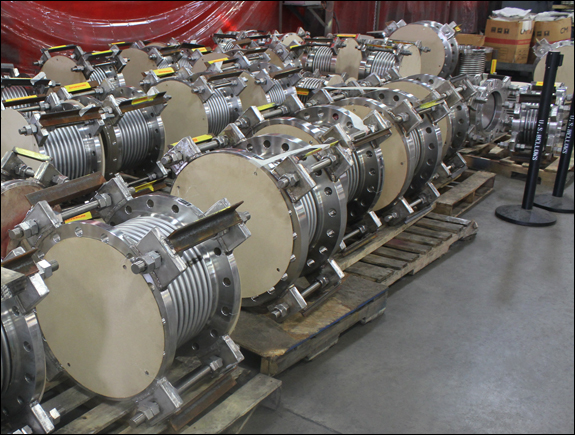
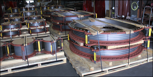
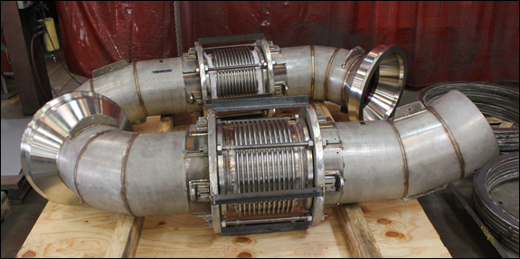
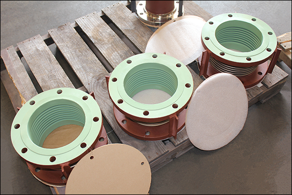
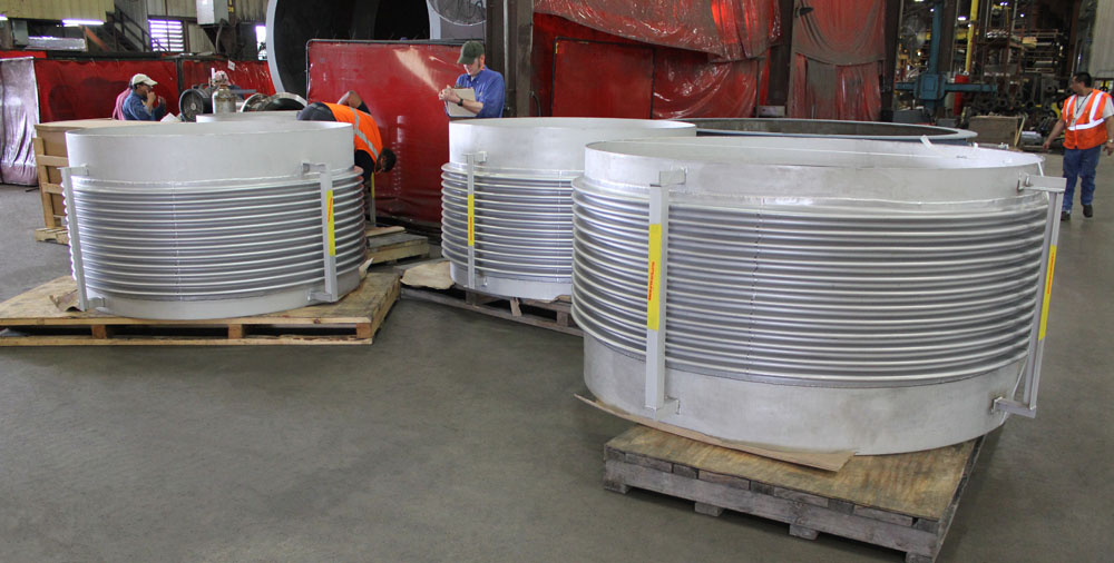
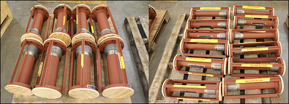
 Notes: