Axial refers to being parallel to the centerline of the pipe expansion joint. Compression is the axial deflection which will shorten the bellows length. Often confusion occurs because thermal expansion in the piping will cause the pipe expansion joint to be compressed. The specification for a pipe expansion joint should always state the movements as they affect the pipe expansion joint, and not as they are produced by the system.
The extension is the axial deflection which stretches the pipe expansion joints. Piping which is operating at temperatures lower than ambient, such as in cryogenic systems, will contract to cause the pipe expansion joint to stretch or experience extension.
|
EXAMPLE 1 |
|
|
|
|
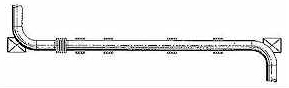
| In this first example, a long straight pipe, anchored at each end, must expand thermally. A single type pipe expansion joint is used with intermediate pipe guides. Good practice dictates that the pipe expansion joint be located as close as possible to one of the anchors, in this case adjacent to the elbow. The first guide should be located as close as possible to the pipe expansion joint, so that the deflection is limited to the expected axial direction. The second guide is located relatively close to the first to prevent any bowing of the pipe, and again to ensure that the end of the pipe at the pipe expansion joint attachment moves in only the expected axial direction. The spacing of the remaining guides should follow the recommendations of the EJMA standards, which are contained in this design manual.
EXAMPLE 2 |
|
|
|
|
|
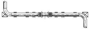
If the straight run of pipe is very long, good practice dictates that the pipe expanding pipe be divided into smaller segments with intermediate anchors. In this way, the pipe’s movement and direction of movement is more safely controlled. A pipe expansion joint is placed between each set of anchors, to absorb the thermal growth of that section of pipe. The above diagram shows this arrangement and the recommended guiding, which is consistent with the discussion in Example 1. EXAMPLE 3 |
|
|
|
|
|
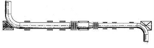
In this example, the same line contains a reducer, and therefore, the pipe run consists of two different diameters. Since the pressure thrust on the main anchors is a function of the pressure times the cross-sectional area of the pipe expansion joints, if only one pipe expansion joint of either pipe size were to be used, a portion of the pressure thrust would exist in the pipe wall as a compression force, tending to buckle or bow the pipe. By locating a main anchor at the reducer, the thermal expansion of each pipe section is confined to that pipe section, and a pipe expansion joint is provided for each section. In this case, the pipe expansion joints are located on either side of the reducer, which satisfies the need to locate them near an anchor. The rules for pipe guiding should be the same as mentioned above. EXAMPLE 4 |
|
 |
|
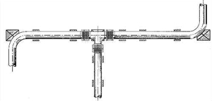
| When another pipe is branching off a long section of straight pipe, the configuration shown above utilizes the Example 2 arrangement for the main pipe section; however, instead of an intermediate anchor, a main anchor should be used at the tee. This main anchor resists the pressure thrust of the branch line. In the direction of the main line the anchor must resist any dynamic pressure thrust imbalance resulting from the changing flow conditions caused by the branch line. Again, all the pipe expansion joints are located near the anchor, and the guiding of all the pipes follows that of Example 1.
EXAMPLE 5 |
|
 |
|
|
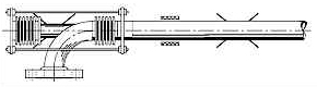
In this example the pipe takes a change in direction with an elbow. The axial thermal expansion of the horizontal pipe is absorbed with a pressure balanced elbow expansion joint so that the main anchor is not required at the elbow. An intermediate anchor is located at the elbow such that the vertical leg does not need to even resist the spring forces of the pipe expansion joint when it deflects. With pressure balanced pipe expansion joints, the pipe wall is in tension, since the pressure thrust is balanced within the pipe and expansion joint. As a result, the extensive guiding provided for the previous examples can be eliminated. Usually, it is good practice to provide at least one guide near the pipe expansion joint, as shown. |