Request A Quote

SAFETY RECOMMENDATIONS FOR PIPING SYSTEMS CONTAINING BELLOWS EXPANSION JOINTS

Bellows pipe expansion joints are employed in piping systems to absorb differential thermal expansion while containing the system pressure. They are being successfully used in refineries, chemical plants, fossil and nuclear power plants, shipboard applications, heating and cooling systems, pulp and paper plants, and cryogenic plants. Typical service conditions range from pressures of full vacuum to 1,000 psig (70 kg/cm3) and -420F to +1,800 F (-251C to +968 C). Thus, pipe expansion joints must be specified as a highly engineered product. They cannot and should not be purchased and used as commodity items if the pipe expansion joints are to perform their intended function safely and reliably. The system operating requirements, the pipe expansion joint design and manufacturing quality, the installation, test and operating procedures must all be considered for all pipe expansion joint installations.

Unlike most commonly used piping components, a bellows is constructed of relatively thin gauge material in order to provide the flexibility needed to absorb mechanical and thermal movements expected in service. This requires design, manufacturing quality, nondestructive examination, handling, installation and inspection procedures which recognize the unique nature of this product.

In general, the most reliable and safe bellows pipe expansion joint installations have always involved a high degree of understanding between the user and manufacturer. With this basic concept in mind, the following recommendations are given in order to better inform the user of those factors which many years of experience have shown to be essential for the successful installation and performance of piping systems containing bellows pipe expansion joints.

Installation & Maintenance (Fabric Expansion Joints)

May 14, 2019

Shipping and Installation of Fabric Expansion Joints

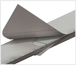
Fabric expansion joints can be shipped in a variety of conditions to allow for the most economical installation. In certain instances, it is practical to ship joints fully assembled ready to drop into place. In other cases where access is limited or joint size exceeds normal shipping constraints, the joint can be broken down into small segments and then assembled in place at the job site. The fabric belt itself may require field splicing which is accomplished with a heat seal iron and splice kit.

U.S. Bellows will provide the appropriate detailed storage, handling, and installation instruction based on how the expansion joint is shipped.

The following section provides an overview of instructions that are available.

FLEXXCEL Installation Instructions

Applicable installation instructions will accompany each expansion joint or fabric belt shipped by U.S. Bellows. These instructions provide clear step by step procedures as outlined on the following pages.

Factory Assembled Fabric Joint Installation Instructions

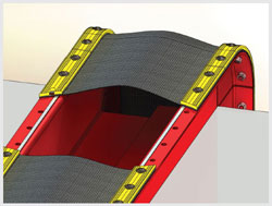
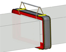
Where conditions allow, fabric expansion joints can be shipped factory assembled, ready to install. The complete joint can be lifted in place with a crane and attached, either by welding or bolting, to ducting or equipment. Read more on factory assembled fabric joint installation instructions.

Factory Unassembled Fabric Joint Installation Instructions

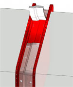
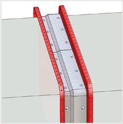
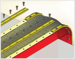
In some instances, it may be preferable to purchase the expansion joint unassembled and complete the assembly of the joint in place on the ducting. In these cases, the frame will typically ship as rails attached to corners for rectangular joints and in c-sections for round joints. The fluoroplastic fabric belt is easy to field drill and splice in place. Read more on factory unassembled fabric joint installation instructions.

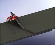
Fluoroplastic Belt Splicing

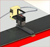
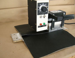
FLEXXCEL Heat Seal Iron

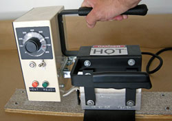
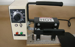
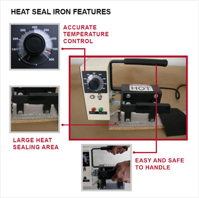
Fluoroplastic fabric gas seal elements often require field splicing during installation and replacement. Cost-effective and easy-to-use heat seal irons are available from U.S. Bellows for purchase or rent. Flexxcel Fluoroplastic fabric gas seal elements are repairable for the life of the material using the heat seal iron.

  1. Learn about the Flexxcel Heat Seal Iron
  2. Single Ply Belt Splice
  3. HT Belt Saddle Splice (High Temperature)
  4. HT Composite Belt Splice (High Temperature)
  5. ensureAsplice Test splice

Properly Installed Expansion Joint Inspections

Do not insulate over the fabric expansion joint unless specified by the U.S. Bellows’ drawing (see below for acceptable duct insulation design) In general, the external insulation should allow access to the belt for inspection and replacement. In high-temperature applications, insulation should be…Read more.

Fabric Expansion Joint Receiving and Storage Instructions

It is the purchaser’s or receiver’s responsibility to witness the unloading of the expansion joints and receiving an inspection to see if there is visual damage to the pallet, box or crate (shipping container) in which the expansion joints were shipped. Any such damage is to be noted on the trucker’s acknowledgment of receipt of the shipment. Failure to note visual damage to the shipping container can … Read more.

Read More
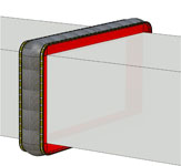
Properly Installed Expansion Joint Inspections

April 22, 2019

PROPERLY INSTALLED EXPANSION JOINT

PRE-START UP INSPECTION

  1. Verify all nuts and bolts are tightened correctly
  2. Check for surface damage on the fabric belt
  3. Remove all debris from expansion joint — i.e. loose nuts & bolts, loose shims, tools, etc.
  4. Remove any obstructions near the expansion joint which may prevent proper air flow and cause over-heating
  5. Verify shipping bars have been removed.

PROPERLY INSTALLED EXTERNAL INSULATION
Do not insulate over the fabric expansion joint unless specified by the U.S. Bellows drawing (see below for acceptable duct insulation design) In general, the external insulation should allow access to the belt for inspection and replacement. In high temperature applications, insulation should be designed to allow thermal convection in the area of the belt attachment. In applications where the temperature is near the due point of the gas, the design should minimize cold spots which could lead to corrosion.

Read More

Ensure-A-Splice, Test Splice

Installation Instructions [PDF]

Splicing of fabric expansion joints is a critical operation which needs to be performed correctly for the expansion joint splice to hold up under system operating conditions. ensureAsplice is the answer to assure that a splice is made correctly.

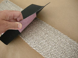
U.S. Bellows material is a thin, flexible, lightweight, PTFE material that clearly indicates when the proper conditions have been established for achieving a successful test splice on FLEXXCEL Fabric Expansion Joint materials. The U.S. Bellows material accomplishes this in two ways. First, a dramatic color change in the product during the splicing procedure ensures that the critical sealing temperature has been reached in the splice area. In addition, the material bonds to the expansion joint’s PTFE surface, confirming that sufficient pressure was applied during the splicing operation.

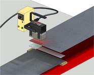
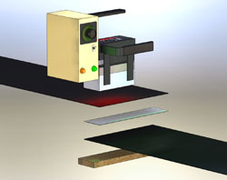
The sealing process requires that all splice components be assembled between the heat sealer and the product. As the splice heats up, the U.S. Bellows product changes from a light shade of red to a much darker shade of the red. The easily observed color change can only take place after the splice components have reached the critical sealing temperature required for PTFE products. If sufficient pressure has been applied as the color change occurs, the product will adhere to the expansion joint’s PTFE surface, confirming that the proper splicing conditions were achieved.

A successfully completed test splice utilizing the ensureAsplice material will ensure that the variables that exist during a field splice have been accounted for. The actual splice on the expansion joint can now be completed with confidence.

Variables to consider:

  • Ambient conditions
  • Length of extension cord
  • Acceptable voltage
  • Proper “backer board” usage
  • Heat Seal Iron in good working condition
  • Allow iron time to reach required temperature
  • Be sure the green light is illuminated
  • Proper amount of time used to splice
  • Proper amount of pressure applied during splice
  • Follow U.S. Bellows splice procedures

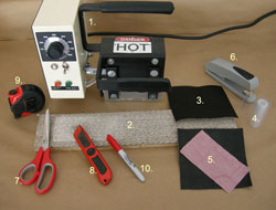
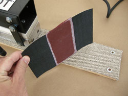
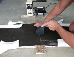
1. Shown are the items required to produce a test splice with the product

  1. Heat Seal Iron
  2. Backer Board
  3. FLEXXCEL belting material
  4. PFA heat sealing film
  5. ensureAsplice product
  6. Stapler
  7. Scissors
  8. Blade Knife
  9. Tape Measurer
  10. Marking Pen

2. Begin by placing the product on the “Backer Board” surface.

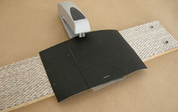
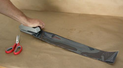
3. Overlap the 2 pieces of FLEXXCEL belt material. The overlap should be the same width as the PFA Film. Make sure the PFA film is residing between the two belt ends in the overlap splice area. Staple the PFA Film in place.

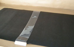
4. Position the ensureAsplice product under the stapled pieces of FLEXXCEL belt material.

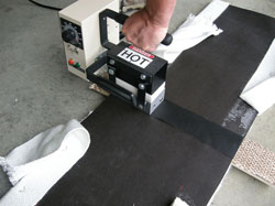
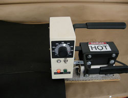
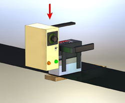
5. Set the heat seal iron at 725°F (385°C). Be sure that the green light illuminates—assuring the iron has reached proper temperature prior to beginning the splice. When the iron reaches desired temperature, place the sealer on the overlap splice.

6, While the heat sealer resides on the splice, apply pressure by pushing down on the handle of the iron. The product darkens in color in the area under the sealer. In “normal” conditions, the iron should stay on the splice area for five minutes. It is a good practice to set a timer, as too much splicing time can be detrimental to the material.

7. Remove the iron from the material. Place the iron on the “Backer Board” while it cools.

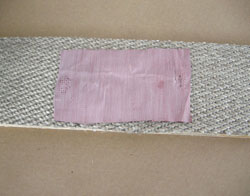
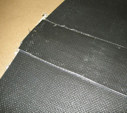
8. Please note that the color of the ensureAsplice material has changed from the color light to dark. The test splice is a success. Actual expansion joint splice can now take place with confidence in equipment and conditions.

9. An inspection of the delaminated splice reveals that in the area where the product darkened in color, a high quality, overlap, heat-sealed, splice was achieved.

Read More

Fluoroplastic Belt Splice, HT Composite Belts

HT Composite Belt Splice

Installation Instructions [PDF]

U.S. Bellows highly recommends that a test splice be performed prior to actual splice.

Thank you for purchasing FLEXXCEL Fabric Expansion Joint material. Prior to performing the actual splice on your expansion joint, please complete a U.S. Bellows Test Splice. Refer to the U.S. Bellows Test Splice instructions for details.

Safety Precautions

Experience has shown fluoropolymers can be processed and used at elevated temperatures without hazard if proper ventilation is used. Make certain all heat sealing is performed in well ventilated areas. Make certain the heat sealer is safely handled during use. The heat sealer temperature will reach 725°F in normal operation. Special care must be taken with the heat sealer during handling due to the high temperature.

Equipment required to splice FLEXXCEL materials:

  1. Heat Seal Iron
  2. Backer Board
  3. FLEXXCEL belting material
  4. PFA heat sealing film
  5. ensureAsplice product
  6. Stapler*
  7. Scissors*
  8. Blade Knife*
  9. Tape Measurer*
  10. Marking Pen*

*These items are not included in the kit.

Heat Seal Iron Operation

To operate the Heat Seal Iron, follow these instructions:

  1. Plug the unit into an electrical outlet.
  2. Place the Heat Seal Iron on the FLEXXCEL Backer Board or another insulated surface.
  3. Push the toggle switch up to the “on” position.
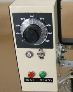
  4. Set the temperature by turning the dial to the desired temperature. A temperature range of 700°-740°F (370°-385°C) is typical for splicing U.S. Bellows FLEXXCEL materials.
  5. If ambient conditions are ideal, each splice section should take approximately 5 minutes.

The unit contains two lights, a “heat up” light and a “ready” light. The “heat up” light will remain lit until the unit reaches the set temperature, at which point the “ready” light will go on.

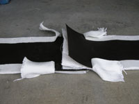
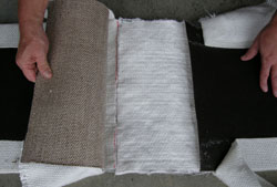
Install the FLEXXCEL HT composite belt material on the expansion joint frames per the belt installation instructions. The Heat Seal Splice should be performed prior to the last backup-bars being installed. The belt ends should overlap 8″ to 12″.

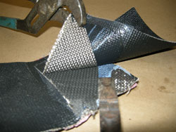
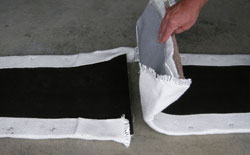
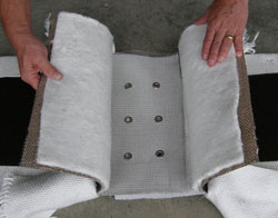
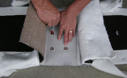
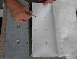
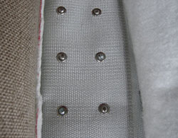
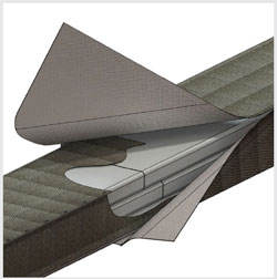
Peel back cuff material. Expose layers of mesh and aluminized cloth. The layer of mesh/cloth that does not contain the grommets should be closest to the gas stream. The layer of mesh/cloth that contains the grommets should be the next layer.

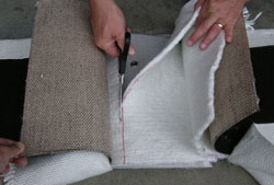
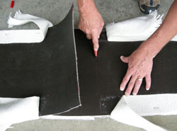
Overlap the layers of insulation. At the end of the overlap, mark the material. Cut the insulation along the mark. The ends of each layer of insulation should “butt up”.

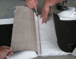
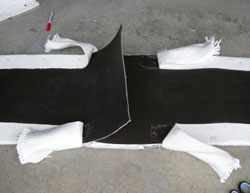
Overlap and mark the outer layer of FLEXXCEL HT material. Score the line with a razor knife. Cut through the entire thickness of the FLEXXCEL HT material

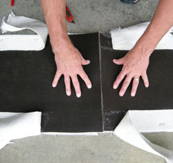
The FLEXXCEL HT belt material is “butted up” and ready to splice. However, first, peel back all materials and expose the cloth and mesh layers. Use the grommets as a guide and mark each hole onto the inner most layer of aluminized cloth.

Punch holes in the bottom layer of cloth. Line up punched holes with the grommets. Install nuts, bolts and washers to secure the layers of cloth/mesh. Hand tighten all nuts.

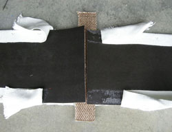
The insulation layers are put back into the “butted up” position. Place the backer board on the insulation layer, under the FLEXXCEL HT material.

Cut PFA film and 3″ wide FLEXXCEL HT material saddle strip to equal the width of the installed belt. Staple the PFA film to the “gas side” of the FLEXXCEL material strip. Place the saddle strip over the butted up FLEXXCEL HT material, the PFA film facing down.

Place the iron at edge of belt to begin splice. Depending on width of belt, it may be necessary to perform multiple splices across the width of the belt. Step iron across width of belt, overlapping each splice 1/2″. Apply pressure to iron handles during each splice. Each splice section should take approximately 5 minutes.

Upon completion of all necessary splices, allow belt to cool prior to additional handling. When sufficiently cooled, place the “cuff” material back into place. Trim excess cuff material.


Clamp the belt and back up bars into place and drill remaining holes in the belt. Bolt the back up bars into place. Expansion joint splice and installation is complete.

Read More
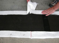
Fluoroplastic Belt Splice, HT Saddle Splice Instructions

HT Saddle Splice Instructions

Installation Instructions [PDF]

U.S. Bellows highly recommends that a test splice be performed prior to actual splice.

Thank you for purchasing FLEXXCEL Fabric Expansion Joint material. Prior to performing the actual splice on your expansion joint, please complete a U.S. Bellows Test Splice. Refer to the U.S. Bellows Test Splice instructions for details.

Safety Precautions

Experience has shown fluoropolymers can be processed and used at elevated temperatures without hazard if proper ventilation is used. Make certain all heat sealing is performed in well ventilated areas. Make certain the heat sealer is safely handled during use. The heat sealer temperature will reach 725°F in normal operation. Special care must be taken with the heat sealer during handling due to the high temperature.

Equipment required to splice FLEXXCEL materials:

  1. Heat Seal Iron
  2. Backer Board
  3. FLEXXCEL belting material
  4. PFA heat sealing film
  5. ensureAsplice product
  6. Stapler*
  7. Scissors*
  8. Blade Knife*
  9. Tape Measurer*
  10. Marking Pen*

*These items are not included in the kit.

Heat Seal Iron Operation

To operate the Heat Seal Iron, follow these instructions:

  1. Plug the unit into an electrical outlet.
  2. Place the Heat Seal Iron on the FLEXXCEL Backer Board or another insulated surface.
  3. Push the toggle switch up to the “on” position.
  4. Set the temperature by turning the dial to the desired temperature. A temperature range of 700°-740°F (370°-385°C) is typical for splicing U.S. Bellows FLEXXCEL materials.
  5. If ambient conditions are ideal, each splice section should take approximately 5 minutes.

The unit contains two lights, a “heat up” light and a “ready” light. The “heat up” light will remain lit until the unit reaches the set temperature, at which point the “ready” light will go on.

Install the FLEXXCEL HT belt material on the expansion joint frames per the BELT INSTALLATION INSTRUCTIONS. Leave section on top of duct “unbolted” at preferred splice area. Carefully trim FLEXXCEL HT belt material so the two ends “butt up” with each other.

Follow Page 1 instructions for iron operating instructions. Cut PFA film and 3″ wide FLEXXCEL material strip to equal the width of the installed belt. Staple the PFA film to the “gas side” of the FLEXXCEL material strip.

Slide the backer board under the splice area. Place the FLEXXCEL material strip over the “trimmed” HT material with the PFA film facing down. Place iron at edge of belt to begin splice. Apply pressure to iron handles during each splice. Each splice section should take approximately 5 minutes.

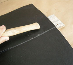
After each section of the splice is complete, rub the completed splice area with a wooden block—or end of a wooden hammer handle. There will be a noticeable change of color on the belt after rubbing. Allow the splice to cool to ambient temperature before further handling the belt. Depending on width of belt, it may be necessary to perform multiple splices across the width of the belt. Step iron across width of belt, overlapping each splice 1/2″.

After the belt has sufficiently cooled, clamp the belt and back up bars into place and drill remaining holes in the belt. Bolt the back up bars into place. Expansion joint splice and installation is complete.

Read More
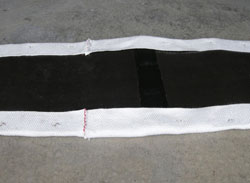
Fluoroplastic Belt Splice, Single Ply Splice

April 20, 2019

Single Ply Splice Instructions

Download Instructions [PDF]

U.S. Bellows highly recommends that a test splice be performed prior to actual splice.

Thank you for purchasing FLEXXCEL Fabric Expansion Joint material. Prior to performing the actual splice on your expansion joint, please complete a U.S. Bellows Test Splice. Refer to the U.S. Bellows Test Splice instructions for details.

Safety Precautions

Experience has shown fluoropolymers can be processed and used at elevated temperatures without hazard if proper ventilation is used. Make certain all heat sealing is performed in well ventilated areas. Make certain the heat sealer is safely handled during use. The heat sealer temperature will reach 725°F in normal operation. Special care must be taken with the heat sealer during handling due to the high temperature.


Equipment required to splice FLEXXCEL materials:

  1. Heat Seal Iron
  2. Backer Board
  3. FLEXXCEL belting material
  4. PFA heat sealing film
  5. ensureAsplice product
  6. Stapler*
  7. Scissors*
  8. Blade Knife*
  9. Tape Measurer*
  10. Marking Pen*

*These items are not included in the kit.

Heat Seal Iron Operation

To operate the Heat Seal Iron, follow these instructions:

  1. Plug the unit into an electrical outlet.
  2. Place the Heat Seal Iron on the FLEXXCEL Backer Board or another insulated surface.
  3. Push the toggle switch up to the “on” position.
  4. Set the temperature by turning the dial to the desired temperature. A temperature range of 700°-740°F (370°-385°C) is typical for splicing U.S. Bellows FLEXXCEL materials.
  5. If ambient conditions are ideal, each splice section should take approximately 5 minutes.

The unit contains two lights, a “heat up” light and a “ready” light. The “heat up” light will remain lit until the unit reaches the set temperature, at which point the “ready” light will go on.
Install the FLEXXCEL belt material per the BELT INSTALLATION INSTRUCTIONS. Heat Seal Splice should be performed prior to last back-up-bars being installed.

  • Place backer board under belt
  • Overlap belt ends
  • Mark belt to allow 3″ overlap
  • Trim excess belt
  • Trim PFA Film to proper width
  • Staple PFA film between belt plies

Make sure the heat sealer has reached the temperature of 700°-740°F before using. (Green light on) Place iron at edge of belt to begin splice. Apply pressure to handles of iron. Leave iron on splice area for 5 minutes. Depending on width of belt, it may be necessary to perform multiple splices across the width of the belt. Step iron cross width of belt, overlapping each splice 1/2″.

After each section of the splice is complete, press/rub the completed spliced area with a wooden block— or the end of a wooden hammer handle. There will be a noticeable change of color on the belt after rubbing. This process will help spread the melted PFA material evenly.

When the heat seal is complete, remove the sealer and place on the backer board to cool. Allow the splice to cool to ambient temperature before further handling the belt.

When entire splice is complete, clamp the back up bars into place and drill remaining holes in the belt. Bolt the back up bars into place. Expansion joint splice and installation is complete.

Read More
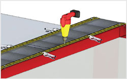
Fluoroplastic Belt Splice, FLEXXCEL Heat Seal Iron

FLEXXCEL Heat Seal Iron

Download Instructions [PDF]

U.S. Bellows manufactures high-performance fabric expansion joints for industrial applications. These expansion joints often require thermal-welding (heat seal splice) in field service. Cost effective and easy-to-use heat seal irons are available from U.S. Bellows for use with FLEXXCEL materials.

The main function of a heat seal iron is to introduce enough heat to allow a proper bond between PTFE surfaces of FLEXXCEL materials. The melting point of PTFE is around 621°F (327°C). However, the setting of a heat seal iron is determined by factors like ambient temperature, thickness of bonding materials, and the surface upon which you heat seal. Applying pressure can help facilitate a good bond, but in order to achieve a correct bond, the melting point of the U.S. Bellows FLEXXCEL materials must be achieved.

Safety Precautions

Experience has shown fluoropolymers can be processed and used at elevated temperatures without hazard if proper ventilation is used. Make certain all heat sealing is performed in well ventilated areas. Make certain the heat sealer is safely handled during use. The heat sealer temperature will reach 725°F in normal operation. Special care must be taken with the heat sealer during handling due to the high temperature.

FLEXXCEL Heat Seal Iron Operation

To operate the Heat Seal Iron, follow these instructions:

  1. Plug the unit into an electrical outlet.
  2. Place the Heat Seal Iron on the FLEXXCEL
  3. Backer Board or another insulated surface.
  4. Push the toggle switch up to the “on” position.
  5. Set the temperature by turning the dial to the desired temperature. A temperature range of 700°-740°F (370-385°C) is typical for splicing FLEXXCEL materials.

The unit contains two lights, a “heat up” light and a “ready” light. The “heat up” light will remain lit until the unit reaches the set temperature, at which point the “ready” light will go on.

Upon purchase or rental of a Flexxcel Heat Seal Iron, U.S. Bellows will supply detailed Heat Seal Splice instructions specific to the belt material that you purchase. These instructions will include text, photos and drawings.
U.S. Bellow will supply a test splice kit utilizing state of the art material – ensureAsplice, which will virtually guarantee that you will perform a successful splice. Detailed test splice instructions will be included.

Product Specifications

Product 3×6 Heat Seal Iron
Platen Dimensions 3” x 6” (75 x 152mm)
Supply Voltage 120 Volts or 240 Volts
Current 7.1 AMPS @ 120 Voluts
3-1/2 AMPS @ 240 Volts
Controller Fenwal Series 54-4
Weight 12.5 lbs (5.7 KG)
Wattage 850 Watts
Frequency 60/50 Hz

Purchase or Rental?

Purchase – FLEXXCEL Heat Seal Irons can be purchased. Contact us for the best purchase price. If the iron is purchased, it should be stored for all future belt installations, or for emergency repairs.
Rental – Flexxcel Heat Seal Irons can be rented on a daily basis with a minimum 3-day rental. Contact us for the best rental price. The iron will be inspected upon return. The Iron must be returned in good working condition.

Read More
Unassembled Fabric Expansion Joint Installation Instructions

Download Instructions [PDF]

Please read entire document prior to beginning Expansion Joint Installation. The recommendations in this document are to be used as a guide. Please use these instructions in conjunction with the approved drawing provided by U.S. Bellows. The approved drawing should be considered the governing document.

Receiving and Storage

Follow U.S. Bellows’ Receiving and Storage Instructions

2. Pre-Installation Checks

  1. Confirm dimensional data per U.S. Bellows’ approved drawing.
  2. Confirm duct/duct flanges are in good condition.
  3. Confirm duct/duct flanges are lined up correctly (ensure that lateral displacement and angular movement do not exceed agreed specifications).
  4. Prior to installing the expansion joint frames, the opening into which the expansion joint will be installed must be inspected to verify that the openings is in accordance with design tolerances. The expansion joint is not designed to accommodate installation misalignment, unless clearly specified as a design requirement.
  5. Make available the following tools/equipment to simplify the installation:
    • Suitable/safe scaffolding
    • Lifting equipment (fork lift, crane, hoist)
    • Drill
    • Come along
    • Rope
    • Pry Bar

3. Expansion Joint Installation

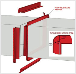
  1. Using the U.S. Bellows drawing, organize the parts per drawing information and “match markings” on parts.
  2. Clean duct/flange surfaces and prepare for welding.
  3. Tack weld frame segments into place. If the expansion joint has a liner, make certain that the flow arrow of the expansion joint/liner is in the proper system flow direction. If liner ships loose, install frames first to allow seal weld access.
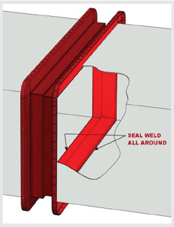
  4. Seal weld frames.
  5. Install accumulation barrier/insulation pillow — if required.

4. Accumulation barriers or Insulation Pillows — IF REQUIRED

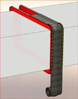
Accumulation Barriers are typically designed to fill the entire cavity of the expansion joint. Wrap the accumulation barrier around the duct/expansion joint. Pack the accumulation barrier into the cavity of the expansion joint. The liner will prevent the barrier from falling into the duct. Use thread or wire to tie across the breach opening to support accumulation barrier during installation. Remove thread or wire prior to installing the fabric belt element.

While splicing or joining the ends of the barrier, “stagger” the overlaps of the materials to prevent thickness build-up.


5. Accumulation barriers or Insulation Pillows — IF REQUIRED

Insulation pillows are typically designed to prevent high temperatures from contacting the fabric belt material; therefore it is critical to attach the pillow in place. There are multiple ways to attach the pillow. Follow U.S. Bellows drawing for details. Pinning the pillow to the liner (as shown) or the frame are common methods of attachment.

While splicing or joining the ends of the barrier, “stagger” the overlaps of the materials to prevent thickness build-up.

Insulation Pillow installation complete.

6. GASKET — IF REQUIRED

Typically, Fluoroelastomer materials do not require gasket material, while Fluoroplastic materials do.U.S. Bellows offers many unique fabric expansion joint belt designs. When required, gasket material is chosen based on application requirements such as temperature, pressure, ease of installation, etc. The U.S. Bellows drawing will indicate where/when gasket material is required.

Single Ply Fluoroplastic Belt less than 600 degrees F.
Expanded PTFE gasket tape is installed on the frame. Place the gasket on the “cavity” side of the belt attachment bolt hole.

Composite Fluoroplastic Belt Greater than 600 degrees F.
High temperature fiberglass material is used in high temperature applications. Some FLEXXCEL composite belts are shipped with the fiberglass gasket attached to the belt as a cuff. Other FLEXXCEL composite belts are shipped with the fiberglass gasket loose. In high temperature applications, the fiberglass gasket should be installed on the belt attachment flange and under the back up bar.

SHIMS
Where two lengths of back-up-bar come together, place a shim under the back-up-bars, spanning the gap. The gap in back-up-bars should not exceed 1/4″.

7. FABRIC BELT – with factory punched holes

If the fabric belt is shipped with factory punched holes, begin installation of one end of the belt at the top of the duct in the center. Leave this area of the belt unattached, as later this will be where the belt splice is performed. Use clamps to position the belt. Be sure to line up the “corner holes” (if rectangle) first, and then begin installing the back-up-bars and bolts, starting in the corner.

At this point, only hand tighten bolts to assure proper fit up around 2/3 of the joint (If the holes do not align, contact U.S. Bellows for advice — do not drill additional holes or modify existing holes). Install approximately 2/3 of the belt and back-up-bars, leaving an open area available to perform the belt splice. Tighten the bolts snugly.

Perform belt splice. Splice techniques vary — based on the fabric belt construction. Follow U.S. bellows splicing procedures for your specific belt requirements. U.S. Bellows recommends that an ensureAsplice test splice be performed prior to actual splice.

After splice is complete, install remaining back-up-bars. Tighten all bolts to 45 Ft. Lbs.

8. FABRIC BELT — without factory punched holes

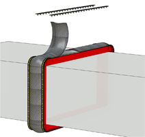
If the fabric belt is shipped without factory punched holes, begin installation of one end of the belt at the top of the duct in the center.

Leave this area of the belt unattached, as later this will be where the belt splice is performed. Use clamps to position the belt and also clamp back-up-bars in place. Using the back-up-bar and frame holes as a guide, drill holes in the belt. At this point, only hand tighten the bolts to assure proper fit up around 2/3 of the joint. Install approximately 2/3 of the belt and back-up-bars, leaving an open area available to perform the belt splice. Tighten bolts snugly.Perform belt splice. Splice techniques vary — based on the fabric belt construction. Follow U.S. Bellows splicing procedures for your specific belt requirements. U.S. Bellows recommends that an ensureAsplice test splice be performed prior to actual splice.

After splice is complete, install remaining back-up-bars. Tighten all bolts to 45 Ft. Lbs.

Read More
Assembled Fabric Expansion Joint Installation Instructions

Download Instructions [PDF]

Please read entire document prior to beginning Expansion Joint Installation. The recommendations in this document are to be used as a guide. Please use these instructions in conjunction with the approved drawing provided by U.S. Bellows. The approved drawing should be considered the governing document.

1. Receiving and Storage

Follow U.S. Bellows’ Receiving and Storage Instructions

2. Pre-Installation Checks

  1. Confirm dimensional data per U.S. Bellows’ approved drawing.
  2. Confirm duct/duct flanges are in good condition.
  3. Confirm duct/duct flanges are lined up correctly (ensure that lateral displacement and angular movement do not exceed agreed specifications)
  4. Prior to installing the expansion joint frames, the opening into which the expansion joint will be installed must be inspected to verify that the opening is in accordance with design tolerances. The expansion joint is not designed to accommodate installation misalignment, unless clearly specified as a design requirement.
  5. Make available the following tools/equipment to simplify the installation:
    • Suitable/safe scaffolding
    • Lifting equipment (fork lift, crane, hoist)
    • Drill
    • Come along
    • Rope
    • Pry Bar

3. Assembled Expansion Joint Installation

  1. Use the U.S. Bellows drawing as a guide for dimensional information.
  2. Clean duct/flange surfaces and prepare for welding or bolting.
  3. Using proper lift equipment, attach suitable lifting “straps” to the expansion joint. Do not lift the expansion joint using the shipping bars.
  4. If the expansion joint has a liner, make certain that the flow arrow of the expansion joint/liner is in the proper system flow direction.

Weld In Design — DUCT IN PLACE

The following instructions are used when ducting is in place and cannot be moved for expansion joint installation.

  1. Lift expansion joint into place using sufficient straps.
  2. Fit up and tack weld one flange of the expansion joint into place. During any welding operation, protect fabric belt material from potential weld splatter.

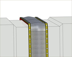
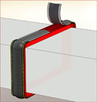
Assembled Fabric Expansion Joint Installation Diagram

Read More
Fabric Expansion Joint Receiving and Storage Instructions

Unloading and Receiving Inspection

It is the purchaser’s or receiver’s responsibility to witness the unloading of the expansion joints and receiving inspection to see if there is visual damage to the pallet, box or crate (shipping container) in which the expansion joints were shipped. Any such damage is to be noted on the trucker’s acknowledgement of receipt of the shipment. Failure to note visual damage to the shipping container can prevent recovery from the shipping company for damage in transit and such unreported damage becomes the responsibility of the purchasing or receiving entity.

If visual damage to the container is apparent, the trucker’s acknowledgement of receipt must be clearly noted as such. The container should be opened and if the contents have been damaged, they should be photographed along with the container. Large expansion joint assemblies may be shipped without a pallet or container of any kind. Under all circumstances, any shipping damage must be immediately reported to U.S. Bellows, (855) 591-0906 and the photographs emailed to sales@devptp.usbellows.com. U.S. Bellows will analyze the damage and provide further instructions.

Storage

Expansion Joints should be stored in a clean and dry environment. However, as a minimum, expansion joints must be stored so that water does not penetrate any closed container. Expansion joints shipped on pallets or shipped without a pallet may be stored out of doors, however it is extremely important that flow liners be in a downward position. Expansion joints with overlapping flow liners should be covered to prevent water from accumulating in the liner.

Installation

Follow ALL U.S. Bellows Installation Instructions provided. Contact U.S. Bellows if Installation Instructions are lost.

Shipping Bars and/or Internal Shipping Restraints

Shipping bars and/or Internal shipping restraints will be painted yellow and marked “Remove after Installation”.

DO NOT REMOVE THE SHIPPING BARS OR INTERNAL RESTRAINTS UNTIL THE EXPANSION JOINT HAS BEEN COMPLETELY INSTALLED.

All assembled expansion joints are shipped to specified “Pre-set” installation dimensions and it is important that the expansion joints are installed accordingly. The “Pre-set” can be Axial (compression or extension), or Lateral, or Angular, or any combination thereof. Expansion Joints will be shipped “Pre-set” in accordance with approved drawing requirements. If the shipping bars are removed prior to completion of installation by bolting or welding, the expansion joint may “move to a neutral position” and will not function as designed and can cause premature or immediate expansion joint failure. For Installation Questions or Clarifications Phone (855) 591-0906 and Refer to the Job Number.

Read More
Top