 |
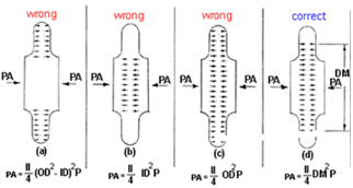
Bellows “PA” (pressure x area) load is frequently misunderstood. This can sometimes lead to serious errors in calculating main anchor design loads. Some common misconceptions are shown below, as well as the correct expression for this load.
- Bellows “PA” load is based on the corrugation sidewall annulus area: WRONGThis is the most serious misconception since it can lead to gross under prediction of the bellows “PA” load and grossly underdesigned main anchors. See Figure “a” below.
- Bellows “PA” load is based on the bellows ID area: WRONGThis misconception can lead to underdesigned anchors, since it ignores the contribution of corrugation sidewall load to total “PA” load. See figure “b” below.
- Bellows “PA” load is based on the bellows OD area: WRONGThis misconception can lead to over predicting the bellows “PA” since it gives too much credit to corrugation sidewall pressure load. See figure “c” below.
- Bellows “PA” load is based on the bellows mean diameter:CORRECTNumerous pressure vs load tests on bellows have shown the mean (or pitch) diameter of the bellows to give very accurate results in predicting bellows pressure thrust. A brief rationale for bellows effective area based on mean diameter is given in para IV. See figure “d” below.
- Thrust Area possibilities:
|
Bellows TID Fluid Area:
It seems reasonably apparent that in a system with a bellows the pipe internal fluid pressure load is not balanced by pipe longitudinal tensile forces and must be restrained by external forces. It can also be seen that if the bellows ID exceeds the pipe ID, an additional pressure force will be transmitted through the pipe as a compression load which must also be externally restrained. Hence one component of the total bellows thrust load is based on the bellows ID. |
|
Bellows ID Area =
|
|
Corrugation Sidewall Thrust:
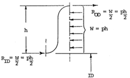
It can also be visualized that internal pressure acting on the sidewall of the corrugation would tend to spread the corrugation out in the longitudinal direction, and this load must be restrained by an external reaction force. As an approximation consider a 1″ wide radial strip cut out of a corrugation.
|
|
|
For a fixed ended beam with uniform load, RID = ROD =  |
| Hence one half of the corrugation sidewall load is carried in tension at the crest of the corrugation. The other half it transmitted through the neck of the corrugation as a compressive force. This force must be resisted by the external main anchors and results in a (generally) small longitudinal compressive stress in the pipe. |
|
Sidewall Effective Area =
But ID + h = mean dia. = Dm
Therefore, Sidewall Effective Area = |
| Total Effective Thrust Area: |
|
Ae=ID area + Sidewall area
Ae= |
| A more precise development of corrugation sidewall load and an equation for bellows effective thrust area is given in the Appendix. A comparison on 5 sample problems of typical bellows dimensions, including one extreme case of OD/ID ratio, shows that the percent error involved in using the mean diameter approximation is generally less than 1% and only 1 1/2% in the extreme example. |
|