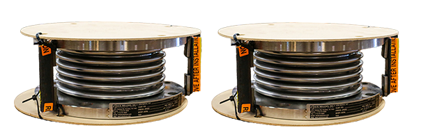
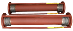
3 inch, 3.5 inch, 4 inch Nominal Diameter
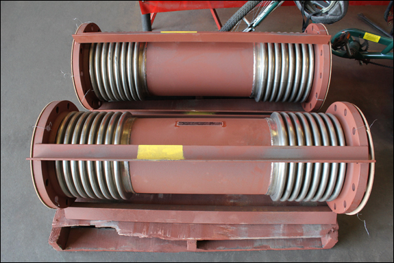
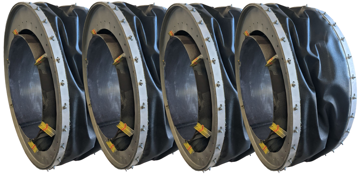
Flanged Universal Expansion Joint
View PDF
Notes:
- Rated life cycle at 650°F is 3000 cycles for any one tabulated movement.
- To combine axial, lateral and angular movements, please refer to the how to order section.
- To increase cycle life or movements, please refer to graph on cycle life.
- Rated bellows extension is equal to rated axial movement. Provided bellows is precompressed the amount of design extension. Installed overall length will decrease by the amount of precompression.
- Tabulated values are for tied joints, with butt weld ends. Performance of joints with flanged ends, and unrestrained joints, will exceed tabulated values.
- Maximum test pressure: 1.5 X rated working pressure.
- Bellows rated for 650°F: See catalog flange data for appropriate flange temperature/pressure ratings.
- Pressure thrust load applied to adjacent pipe anchors/equipment when unrestrained expansion joints are used.
| Size | Pressure | Non-concurrant Movements/Spring Rates |
| Lateral Movement/Spring Rates | Axial |
| 24 | in.
Overall Length | 36 | in.
Overall Length | 48 | in.
Overall Length | Movement | Spring Rate |
| 610 | mm
Overall Length | 914 | mm
Overall Length | 1219 | mm
Overall Length |
| Movement | Spring
Rate | Movement | Spring
Rate | Movement | Spring
Rate |
| PSIG | in. | lb./in. | in. | lb./in. | in. | lb./in. | in. | lb./in. |
| kg/cm 2 | mm | kg/mm | mm | kg/mm | mm | kg/mm | mm | kg/mm |
| 3 | 75 | 3.17 | 16 | 8.93 | 3 | 14.93 | 1 | 2.05 | 152 |
| 5.3 | 81 | 0.3 | 227 | 0.05 | 379 | 0.02 | 52 | 3 |
| 500 | 1.33 | 91 | 3.39 | 18 | 5.49 | 7 | 0.71 | 1010 |
| 35.1 | 34 | 1.6 | 86 | 0.32 | 139 | 0.13 | 18 | 18 |
| 3.5 | 75 | 2.81 | 23 | 7.82 | 4 | 13.03 | 2 | 2 | 175 |
| 5.3 | 71 | 0.4 | 199 | 0.07 | 331 | 0.04 | 51 | 3 |
| 500 | 1.1 | 151 | 2.77 | 30 | 4.48 | 12 | 0.65 | 1355 |
| 35.1 | 28 | 2.7 | 70 | 0.54 | 114 | 0.21 | 17 | 24 |
| 4 | 50 | 3.43 | 19 | 9.41 | 3 | 15.61 | 1 | 2.71 | 111 |
| 3.5 | 87 | 0.3 | 239 | 0.05 | 396 | 0.02 | 69 | 2 |
| 275 | 1.44 | 106 | 3.53 | 22 | 5.66 | 9 | 0.92 | 775 |
| 19.3 | 37 | 1.9 | 90 | 0.39 | 144 | 0.16 | 23 | 14 |
Materials
Bellows: A240-T304. Alternate materials available upon request. Refer to the materials section.
Flanges: ASTM A105.
50-75 PSIG Series: 150 lb. ANSI B16.5 RPSO.
275-500 PSIG Series: 300 lb. ANSI B16.5 RPSO
Plate flanges and angle flanges available for low pressure systems.
Pipe: ASTM A-53/A-106.
50-75 PSIG Series: Std. Wt. Pipe.
275-500 PSIG Series: Std. Wt. Pipe
Liners: A240-T304.
Covers: Carbon steel.
Tie Rods, Hinges, Gimbals: Carbon steel
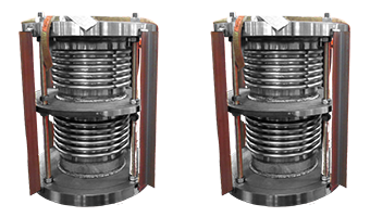
5 inch, 6 inch, 8 inch Nominal Diameter
Flanged Universal Exapnsion Joint
View PDF
Notes:
- Rated life cycle at 650°F is 3000 cycles for any one tabulated movement.
- To combine axial, lateral and angular movements, please refer to the how to order section.
- To increase cycle life or movements, please refer to graph on cycle life.
- Rated bellows extension is equal to rated axial movement. Provided bellows is precompressed the amount of design extension. Installed overall length will decrease by the amount of precompression.
- Tabulated values are for tied joints, with butt weld ends. Performance of joints with flanged ends, and unrestrained joints, will exceed tabulated values.
- Maximum test pressure: 1.5 X rated working pressure.
- Bellows rated for 650°F: See catalog flange data for appropriate flange temperature/pressure ratings.
- Pressure thrust load applied to adjacent pipe anchors/equipment when unrestrained expansion joints are used.
| Size | Pressure | Non-concurrant Movements/ Spring Rates |
| Lateral Movement/Spring Rates | Axial |
| 30 | in.
OverallLength | 42 | in.
OverallLength | 54 | in.
OverallLength | Movement | Spring Rate |
| 762 | mm
OverallLength | 1067 | mm | 1372 | mm
OverallLength |
| Movement | Spring
Rate | Movement | Spring
Rate | Movement | Spring
Rate |
| PSIG | in. | lb./in. | in. | lb./in. | in. | lb./in. | in. | lb./in. |
| kg/cm 2 | mm | kg/mm | mm | kg/mm | mm | kg/mm | mm | kg/mm |
| 5 | 75 | 4.96 | 12 | 9.61 | 4 | 14.33 | 2 | 2.47 | 139 |
| 5.3 | 126 | 0.2 | 244 | 0.07 | 364 | 0.04 | 63 | 2 |
| 275 | 1.78 | 87 | 3.26 | 29 | 4.75 | 14 | 0.77 | 1160 |
| 19.3 | 45 | 1.6 | 83 | 0.52 | 121 | 0.25 | 20 | 21 |
| 6 | 70 | 3.59 | 22 | 7.44 | 6 | 11.34 | 3 | 2.43 | 143 |
| 4.9 | 91 | 0.4 | 189 | 0.11 | 288 | 0.05 | 62 | 3 |
| 200 | 2.01 | 104 | 4.17 | 29 | 6.36 | 13 | 1.36 | 665 |
| 14.1 | 51 | 1.9 | 106 | 0.52 | 162 | 0.23 | 35 | 12 |
| 500 | 0.65 | 1017 | 1.38 | 259 | 2.12 | 115 | 0.46 | 5473 |
| 35.1 | 17 | 18.2 | 35 | 4.63 | 54 | 2.06 | 12 | 98 |
| 8 | 45 | 3.62 | 40 | 8.31 | 10 | 13.19 | 4 | 3.91 | 126 |
| 3.2 | 92 | 0.7 | 211 | 0.18 | 335 | 0.07 | 99 | 2 |
| 200 | 1.89 | 186 | 4.34 | 46 | 6.89 | 20 | 2.05 | 583 |
| 14.1 | 48 | 3.3 | 110 | 0.82 | 175 | 0.36 | 52 | 10 |
| 400 | 0.71 | 1576 | 1.66 | 364 | 2.64 | 157 | 0.77 | 4314 |
| 28.1 | 18 | 28.2 | 42 | 6.51 | 67 | 2.81 | 20 | 77 |
Materials
Bellows: A240-T304. Alternate materials available upon request. Refer to the materials section.
Flanges: ASTM A105.
40-75 PSIG Series: 150 lb. ANSI B16.5 RFSO.
200-275 PSIG Series: 150 lb. ANSI B16.5 RFSO
400-500 PSIG Series: 300 lb. ANSI B16.5 RFSO
Plate flanges and angle flanges available for low pressure systems.
Pipe: ASTM A-53/A-106.
40-75 PSIG Series: Std. Wt. Pipe.
200-275 PSIG Series: Std. Wt. Pipe.
400-500 PSIG Series: Std. Wt. Pipe.
Liners: A240-T304.
Covers: Carbon steel.
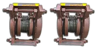
10 inch, 12 inch, 14 inch Nominal Diameter
Flanged Universal Expansion Joint
View PDF
Notes:
- Rated life cycle at 650°F is 3000 cycles for any one tabulated movement.
- To combine axial, lateral and angular movements, please refer to the how to order section.
- To increase cycle life or movements, please refer to graph on cycle life.
- Rated bellows extension is equal to rated axial movement. Provided bellows is precompressed the amount of design extension. Installed overall length will decrease by the amount of precompression.
- Tabulated values are for tied joints, with butt weld ends. Performance of joints with flanged ends, and unrestrained joints, will exceed tabulated values.
- Maximum test pressure: 1.5 X rated working pressure.
- Bellows rated for 650°F: See catalog flange data for appropriate flange temperature/pressure ratings.
- Pressure thrust load applied to adjacent pipe anchors/equipment when unrestrained expansion joints are used.
| Size | Pressure | Non-concurrant Movements/ Spring Rates |
| Lateral Movement/Spring Rates | Axial |
| 24 | in.
Overall Length | 36 | in.
Overall Length | 48 | in.
Overall Length | Movement | Spring Rate |
| 610 | mm
Overall Length | 914 | mm
Overall Length | 1219 | mm
Overall Length |
| Movement | Spring
Rate | Movement | Spring
Rate | Movement | Spring
Rate |
| PSIG | in. | lb./in. | in. | lb./in. | in. | lb./in. | in. | lb./in. |
| kg/cm 2 | mm | kg/mm | mm | kg/mm | mm | kg/mm | mm | kg/mm |
| 10 | 45 | 6.26 | 49 | 11.8 | 18 | 17.63 | 9 | 6.08 | 213 |
| 3.2 | 159 | 0.9 | 300 | 0.32 | 448 | 0.16 | 154 | 4 |
| 260 | 2.72 | 256 | 5.04 | 92 | 7.45 | 47 | 2.48 | 1127 |
| 18.3 | 69 | 4.6 | 128 | 1.65 | 189 | 0.84 | 63 | 20 |
| 12 | 45 | 5.07 | 80 | 10.01 | 27 | 15.23 | 13 | 6.4 | 208 |
| 3.2 | 129 | 1.4 | 254 | 0.48 | 387 | 0.23 | 163 | 4 |
| 200 | 2.41 | 369 | 4.67 | 123 | 7.02 | 60 | 2.85 | 976 |
| 14.1 | 61 | 6.6 | 119 | 2.2 | 178 | 1.07 | 72 | 17 |
| 14 | 50 | 4.8 | 95 | 9.24 | 33 | 13.9 | 16 | 6.23 | 229 |
| 3.5 | 122 | 1.7 | 235 | 0.59 | 353 | 0.29 | 158 | 4 |
| 200 | 2.04 | 548 | 3.92 | 184 | 5.87 | 91 | 2.56 | 1255 |
| 14.1 | 52 | 9.8 | 100 | 3.29 | 149 | 1.63 | 65 | 22 |
Materials
Bellows: A240-T304. Alternate materials available upon request. Refer to the materials section.
Flanges: ASTM A105.
45-50 PSIG Series: 150 lb. ANSI B16.5 RPSO.
200-260 PSIG Series: 300 lb. ANSI B16.5 RPSO
Plate flanges and angle flanges available for low pressure systems.
Pipe: ASTM A-53/A-106.
45-50 PSIG Series: Std. Wt. Pipe.
200-260 PSIG Series: Std. Wt. Pipe
Liners: A240-T304.
Covers: Carbon steel.
Tie Rods, Hinges, Gimbals: Carbon Steel
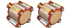
16 inch, 18 inch, 20 inch Nominal Diameter
Flanged Universal Expansion Joint
View PDF
Notes:
- Rated life cycle at 650°F is 3000 cycles for any one tabulated movement.
- To combine axial, lateral and angular movements, please refer to the how to order section.
- To increase cycle life or movements, please refer to graph on cycle life.
- Rated bellows extension is equal to rated axial movement. Provided bellows is precompressed the amount of design extension. Installed overall length will decrease by the amount of precompression.
- Tabulated values are for tied joints, with butt weld ends. Performance of joints with flanged ends, and unrestrained joints, will exceed tabulated values.
- Maximum test pressure: 1.5 X rated working pressure.
- Bellows rated for 650°F: See catalog flange data for appropriate flange temperature/pressure ratings.
- Pressure thrust load applied to adjacent pipe anchors/equipment when unrestrained expansion joints are used.
| Size | Pressure | Non-concurrant Movements/ Spring Rates |
| Lateral Movement/Spring Rates | Axial |
| 48 | in.
Overall Length | 60 | in.
Overall Length | 72 | in.
Overall Length | Movement | Spring Rate |
| 1219 | mm
Overall Length | 1524 | mm
Overall Length | 1829 | mm
Overall Length |
| Movement | Spring
Rate | Movement | Spring
Rate | Movement | Spring
Rate |
| PSIG | in. | lb./in. | in. | lb./in. | in. | lb./in. | in. | lb./in. |
| kg/cm 2 | mm | kg/mm | mm | kg/mm | mm | kg/mm | mm | kg/mm |
| 16 | 35 | 6.73 | 70 | 11.6 | 29 | 16.7 | 16 | 7.75 | 211 |
| 2.5 | 171 | 1.3 | 295 | 0.52 | 424 | 0.29 | 197 | 4 |
| 200 | 3.11 | 339 | 5.06 | 149 | 7.05 | 83 | 2.96 | 1235 |
| 14.1 | 79 | 6.1 | 129 | 2.67 | 179 | 1.49 | 75 | 22 |
| 400 | 2.45 | 843 | 3.98 | 363 | 5.54 | 200 | 2.3 | 2894 |
| 28.1 | 62 | 15.1 | 101 | 6.5 | 141 | 3.58 | 58 | 52 |
| 18 | 40 | 5.91 | 98 | 10.18 | 41 | 14.66 | 22 | 7.59 | 238 |
| 2.8 | 150 | 1.8 | 259 | 0.73 | 372 | 0.39 | 193 | 4 |
| 200 | 2.48 | 550 | 4.16 | 230 | 5.88 | 125 | 2.85 | 1394 |
| 14.1 | 63 | 9.8 | 106 | 4.12 | 149 | 2.24 | 72 | 25 |
| 400 | 1.97 | 1365 | 3.16 | 595 | 4.37 | 331 | 1.98 | 3919 |
| 28.1 | 50 | 24.4 | 80 | 10.65 | 111 | 5.92 | 50 | 70 |
| 20 | 45 | 5.24 | 133 | 9.03 | 55 | 12.99 | 30 | 7.43 | 265 |
| 3.2 | 133 | 2.4 | 229 | 0.98 | 330 | 0.54 | 189 | 5 |
| 200 | 2.26 | 725 | 3.75 | 306 | 5.27 | 167 | 2.77 | 1533 |
| 14.1 | 57 | 13 | 95 | 5.48 | 134 | 2.99 | 70 | 28 |
| 400 | 1.59 | 2120 | 2.62 | 881 | 3.66 | 479 | 1.88 | 4365 |
| 28.1 | 40 | 37.9 | 67 | 15.77 | 93 | 8.57 | 48 | 78 |
Materials
Bellows: A240-T304. Alternate materials available upon request. Refer to the materials section.
Flanges: ASTM A105.
35-45 PSIG Series: 125 lb. Lt/Wt FFSO.
200 PSIG Series: 150 lb. ANSI B16.5 RFSO
400 PSIG Series: 300 lb. ANSI B16.5 RFSO
Plate flanges and angle flanges available for low pressure systems.
Pipe: ASTM A-53/A-106.
35-45 PSIG Series: Std. Wt. Pipe.
200 PSIG Series: Std. Wt. Pipe.
400 PSIG Series: Std. Wt. Pipe.
Liners: A240-T304.
Covers: Carbon steel.
Tie Rods, Hinges, Gimbals: Carbon steel
22 inch, 24 inch, 26 inch Nominal Diameter
Flanged Universal Expansion Joint
View PDF
Notes:
- Rated life cycle at 650°F is 3000 cycles for any one tabulated movement.
- To combine axial, lateral and angular movements, please refer to the how to order section.
- To increase cycle life or movements, please refer to graph on cycle life.
- Rated bellows extension is equal to rated axial movement. Provided bellows is precompressed the amount of design extension. Installed overall length will decrease by the amount of precompression.
- Tabulated values are for tied joints, with butt weld ends. Performance of joints with flanged ends, and unrestrained joints, will exceed tabulated values.
- Maximum test pressure: 1.5 X rated working pressure.
- Bellows rated for 650°F: See catalog flange data for appropriate flange temperature/pressure ratings.
- Pressure thrust load applied to adjacent pipe anchors/equipment when unrestrained expansion joints are used.
|
Size
|
Pressure
|
Non-concurrant Movements/Spring Rates
|
|
Lateral Movement/Spring Rates
|
Axial
|
|
48
|
in.
Overall Length
|
60
|
in.
Overall Length
|
72
|
in.
Overall Length
|
Movement
|
Spring Rate
|
|
1219
|
mm
Overall Length
|
1524
|
mm
Overall Length
|
1829
|
mm
Overall Length
|
|
Movement
|
Spring Rate
|
Movement
|
Spring Rate
|
Movement
|
Spring Rate
|
|
PSIG
|
in.
|
lb./in.
|
in.
|
lb./in.
|
in.
|
lb./in.
|
in.
|
lb./in.
|
|
kg/cm2
|
mm
|
kg/mm
|
mm
|
kg/mm
|
mm
|
kg/mm
|
mm
|
kg/mm
|
|
22
|
45
|
5.28
|
137
|
8.88
|
58
|
12.62
|
32
|
7.62
|
243
|
|
3.2
|
134
|
2.5
|
226
|
1.04
|
321
|
0.57
|
194
|
4
|
|
165
|
2.24
|
811
|
3.66
|
347
|
5.12
|
191
|
2.9
|
1497
|
|
11.6
|
57
|
14.5
|
93
|
6.21
|
130
|
3.42
|
74
|
27
|
|
350
|
1.48
|
2536
|
2.40
|
1069
|
3.33
|
585
|
1.84
|
4506
|
|
24.6
|
38
|
45.4
|
61
|
19.13
|
85
|
10.47
|
47
|
81
|
|
24
|
50
|
4.74
|
177
|
7.98
|
75
|
11.34
|
41
|
7.43
|
266
|
|
3.5
|
120
|
3.2
|
203
|
1.34
|
288
|
0.73
|
189
|
5
|
|
160
|
2.06
|
1024
|
3.36
|
441
|
4.68
|
243
|
2.85
|
1636
|
|
11.2
|
52
|
18.3
|
85
|
7.89
|
119
|
4.35
|
72
|
29
|
|
350
|
1.34
|
3163
|
2.15
|
1347
|
2.97
|
741
|
1.75
|
4925
|
|
24.6
|
34
|
56.6
|
55
|
24.11
|
75
|
13.26
|
44
|
88
|
|
26
|
50
|
3.88
|
268
|
6.83
|
107
|
9.91
|
57
|
7.37
|
289
|
|
3.5
|
99
|
4.8
|
173
|
1.91
|
252
|
1.02
|
187
|
5
|
|
165
|
1.87
|
1450
|
3.41
|
544
|
5.02
|
281
|
3.85
|
1332
|
|
11.6
|
47
|
25.9
|
87
|
9.74
|
128
|
5.03
|
98
|
24
|
|
335
|
1.55
|
3635
|
2.99
|
1252
|
4.52
|
622
|
3.67
|
2672
|
|
23.5
|
39
|
65.1
|
76
|
22.41
|
115
|
11.13
|
93
|
48
|
Materials
Bellows: A240-T304. Alternate materials available upon request. Refer to the materials section.
Flanges: ASTM A105.
45-50 PSIG Series: 125 lb. Lt/Wt FFSO
160-165 PSIG Series: 150 lb. ANSI B16.5 RFSO
335-350 PSIG Series: 300 lb. ANSI B16.5 RFSO
Plate flanges and angle flanges available for low pressure systems.
Pipe: ASTM A-53/A-106/A-285-C
45-50 PSIG Series: Std. Wt. Pipe/0.375-inch wall.
160-165 PSIG Series: Std. Wt. Pipe/0.375-inch wall.
335-350 PSIG Series: 0.500-inch wall.
Liners: A240-T304.
Covers: Carbon steel.
Tie Rods, Hinges, Gimbals: Carbon steel
28 inch, 30 inch, 32 inch Nominal Diameter
Flanged Universal Expansion Joint
View PDF
Notes:
- Rated life cycle at 650°F is 3000 cycles for any one tabulated movement.
- To combine axial, lateral and angular movements, please refer to the how to order section.
- To increase cycle life or movements, please refer to graph on cycle life.
- Rated bellows extension is equal to rated axial movement. Provided bellows is precompressed the amount of design extension. Installed overall length will decrease by the amount of precompression.
- Tabulated values are for tied joints, with butt weld ends. Performance of joints with flanged ends, and unrestrained joints, will exceed tabulated values.
- Maximum test pressure: 1.5 X rated working pressure.
- Bellows rated for 650°F: See catalog flange data for appropriate flange temperature/pressure ratings.
- Pressure thrust load applied to adjacent pipe anchors/equipment when unrestrained expansion joints are used.
| Size | Pressure | Non-concurrant Movements/Spring Rates |
| Lateral Movement/Spring Rates | Axial |
| 48 | in.
Overall Length | 60 | in.
Overall Length | 72 | in.
Overall Length | Movement | Spring
Rate |
| 1219 | mm
Overall Length | 1524 | mm
Overall Length | 1829 | mm
Overall Length |
| Movement | Spring
Rate | Movement | Spring
Rate | Movement | Spring
Rate |
| PSIG | in. | lb./in. | in. | lb./in. | in. | lb./in. | in. | lb./in. |
| kg/cm 2 | mm | kg/mm | mm | kg/mm | mm | kg/mm | mm | kg/mm |
| 28 | 50 | 3.61 | 333 | 6.36 | 132 | 9.22 | 70 | 7.36 | 311 |
| 3.5 | 92 | 6 | 162 | 2.36 | 234 | 1.25 | 187 | 6 |
| 160 | 1.74 | 1801 | 3.17 | 675 | 4.67 | 348 | 3.85 | 1437 |
| 11.2 | 44 | 32.2 | 81 | 12.08 | 119 | 6.23 | 98 | 26 |
| 315 | 1.45 | 4512 | 2.82 | 1554 | 4.25 | 772 | 3.71 | 2881 |
| 22.1 | 37 | 80.7 | 72 | 27.81 | 108 | 13.82 | 94 | 52 |
| 30 | 50 | 3.65 | 316 | 6.41 | 126 | 9.3 | 67 | 7.96 | 257 |
| 3.5 | 93 | 5.7 | 163 | 2.25 | 236 | 1.2 | 202 | 5 |
| 135 | 1.91 | 1708 | 3.48 | 640 | 5.13 | 330 | 4.53 | 1185 |
| 9.5 | 49 | 30.6 | 88 | 11.45 | 130 | 5.91 | 115 | 21 |
| 290 | 1.55 | 4276 | 3 | 1473 | 4.52 | 731 | 4.23 | 2376 |
| 20.4 | 39 | 76.5 | 76 | 26.36 | 115 | 13.08 | 107 | 43 |
| 32 | 50 | 3.43 | 382 | 6.03 | 152 | 8.75 | 80 | 7.96 | 274 |
| 3.5 | 87 | 6.8 | 153 | 2.72 | 222 | 1.43 | 202 | 5 |
| 135 | 1.79 | 2062 | 3.27 | 773 | 4.82 | 399 | 4.53 | 1266 |
| 9.5 | 45 | 36.5 | 83 | 13.83 | 122 | 7.14 | 115 | 23 |
| 290 | 1.45 | 5163 | 2.81 | 1778 | 4.25 | 883 | 4.23 | 2537 |
| 20.4 | 37 | 92.4 | 71 | 31.82 | 108 | 15.8 | 107 | 45 |
Materials
Bellows: A240-T304. Alternate materials available upon request. Refer to the materials section.
Flanges: ASTM A105.
50 PSIG Series: 125 lb Lt/Wt FFSO.
For 135-160 PSIG Series and 290-315 PSIG Series: Customer to specify actual flanges required.
Plate flanges and angle flanges available for low pressure systems.
Pipe: ASTM A-53/APJ-5L/A-285-C.
50 PSIG Series: 0.375-inch wall.
135-160 PSIG Series: 0.375-inch wall.
290-315 PSIG Series: 0.500-inch wall.
Liners: A240-T304.
Covers: Carbon steel.
Tie Rods, Hinges, Gimbals: Carbon steel
34 inch, 36 inch, 38 inch Nominal Diameter
Flanged Universal Expasnion Joint
View PDF
Notes:
- Rated life cycle at 650°F is 3000 cycles for any one tabulated movement.
- To combine axial, lateral and angular movements, please refer to the how to order section.
- To increase cycle life or movements, please refer to graph on cycle life.
- Rated bellows extension is equal to rated axial movement. Provided bellows is precompressed the amount of design extension. Installed overall length will decrease by the amount of precompression.
- Tabulated values are for tied joints, with butt weld ends. Performance of joints with flanged ends, and unrestrained joints, will exceed tabulated values.
- Maximum test pressure: 1.5 X rated working pressure.
- Bellows rated for 650°F: See catalog flange data for appropriate flange temperature/pressure ratings.
- Pressure thrust load applied to adjacent pipe anchors/equipment when unrestrained expansion joints are used.
| Size | Pressure | Non-concurrant Movements/Spring Rates |
| Llateral Movement/Spring Rates | Axial |
| 54 | in.
Overall Length | 66 | in.
Overall Length | 78 | in.
Overall Length | Movement | Spring Rate |
| 1372 | mm
Overall Length | 1676 | mm
Overall Length | 1981 | mm
Overall Length |
| Movement | Spring
Rate | Movement | Spring
Rate | Movement | Spring
Rate |
| PSIG | in. | lb./in. | in. | lb./in. | in. | lb./in. | in. | lb./in. |
| kg/cm 2 | mm | kg/mm | mm | kg/mm | mm | kg/mm | mm | kg/mm |
| 34 | 50 | 4.44 | 273 | 6.97 | 129 | 9.56 | 74 | 7.96 | 292 |
| 3.5 | 113 | 4.9 | 177 | 2.31 | 243 | 1.32 | 202 | 5 |
| 135 | 2.13 | 1683 | 3.54 | 723 | 5.01 | 398 | 4.5 | 1346 |
| 9.5 | 54 | 30.1 | 90 | 12.94 | 127 | 7.12 | 114 | 24 |
| 275 | 1.58 | 4951 | 2.89 | 1856 | 4.25 | 958 | 4.24 | 2699 |
| 19.3 | 40 | 88.6 | 73 | 33.21 | 108 | 17.14 | 108 | 48 |
| 36 | 50 | 4.21 | 323 | 6.59 | 152 | 9.05 | 88 | 7.96 | 309 |
| 3.5 | 107 | 5.8 | 167 | 2.72 | 230 | 1.57 | 202 | 6 |
| 135 | 2.02 | 1991 | 3.35 | 854 | 4.74 | 471 | 4.49 | 1427 |
| 9.5 | 51 | 35.6 | 85 | 15.28 | 120 | 8.43 | 114 | 26 |
| 250 | 1.52 | 5853 | 2.78 | 2194 | 4.09 | 1132 | 4.31 | 2860 |
| 17.6 | 39 | 104.7 | 71 | 39.26 | 104 | 20.26 | 109 | 51 |
| 38 | 50 | 3.99 | 379 | 6.26 | 179 | 8.59 | 103 | 7.96 | 327 |
| 3.5 | 101 | 6.8 | 159 | 3.2 | 218 | 1.84 | 202 | 6 |
| 130 | 1.93 | 2333 | 3.21 | 1001 | 4.53 | 552 | 4.52 | 1508 |
| 9.1 | 49 | 41.8 | 82 | 17.91 | 115 | 9.88 | 115 | 27 |
| 250 | 1.44 | 6859 | 2.64 | 2571 | 3.88 | 1327 | 4.3 | 3021 |
| 17.6 | 37 | 122.7 | 67 | 46.01 | 99 | 23.75 | 109 | 54 |
Materials
Bellows: A240-T304. Alternate materials available upon request. Refer to the materials section.
Flanges: ASTM A105.
50 PSIG Series: 125 lb. Lt/Wt FFSO.
For 130-135 PSIG Series and 250-275 PSIG Series: Customer to specify actual flanges required.
Plate flanges and angle flanges available for low pressure systems.
Pipe: ASTM A-285-C.
50 PSIG Series: 0.375-inch wall
130-135 PSIG Series: 0.375-inch wall.
250-275 PSIG Series: 0.500-inch wall.
Liners: A240-T304.
Covers: Carbon steel.
Tie Rods, Hinges, Gimbals: Carbon steel
40 Inch, 42 inch Nominal Diameter
Flanged Universal Expansion Joint
View PDF
Notes:
- Rated life cycle at 650°F is 3000 cycles for any one tabulated movement.
- To combine axial, lateral and angular movements, please refer to the how to order section
- To increase cycle life or movements, please refer to graph on cycle life.
- Rated bellows extension is equal to rated axial movement. Provided bellows is precompressed the amount of design extension. Installed overall length will decrease by the amount of precompression.
- Tabulated values are for tied joints, with butt weld ends. Performance of joints with flanged ends, and unrestrained joints, will exceed tabulated values.
- Maximum test pressure: 1.5 X rated working pressure.
- Bellows rated for 650°F: See catalog flange data for appropriate flange temperature/pressure ratings.
- Pressure thrust load applied to adjacent pipe anchors/equipment when unrestrained expansion joints are used.
| Size | Pressure | Non-concurrant Movements/Spring Rates |
| Lateral Movement/Spring Rates | Axial |
| 54 | in.
Overall Length | 66 | in.
Overall Length | 78 | in.
Overall Length | Movement | Spring
Rate |
| 1372 | mm
Overall Length | 1676 | mm
Overall Length | 1981 | mm
Overall Length |
| Movement | Spring
Rate | Movement | Spring
Rate | Movement | Spring
Rate |
| PSIG | in. | lb./in. | in. | lb./in. | in. | lb./in. | in. | lb./in. |
| kg/cm 2 | mm | kg/mm | mm | kg/mm | mm | kg/mm | mm | kg/mm |
| 40 | 50 | 3.45 | 515 | 5.59 | 231 | 7.8 | 130 | 7.96 | 344 |
| 3.5 | 88 | 9.2 | 142 | 4.13 | 198 | 2.33 | 202 | 6 |
| 120 | 1.66 | 3254 | 2.88 | 1312 | 4.15 | 700 | 4.58 | 1588 |
| 8.4 | 42 | 58.2 | 73 | 23.48 | 105 | 12.53 | 116 | 28 |
| 225 | 1.21 | 9928 | 2.35 | 3419 | 3.55 | 1698 | 4.37 | 3183 |
| 15.8 | 31 | 177.7 | 60 | 61.18 | 90 | 30.39 | 111 | 57 |
| 42 | 50 | 3.29 | 595 | 5.34 | 267 | 7.45 | 150 | 7.96 | 362 |
| 3.5 | 84 | 10.6 | 136 | 4.78 | 189 | 2.68 | 202 | 6 |
| 115 | 1.59 | 3756 | 2.77 | 1514 | 3.99 | 809 | 4.61 | 1669 |
| 8.1 | 40 | 67.2 | 70 | 27.09 | 101 | 14.48 | 117 | 30 |
| 225 | 1.16 | 11459 | 2.24 | 3946 | 3.39 | 1960 | 4.37 | 3344 |
| 15.8 | 29 | 205.1 | 57 | 70.62 | 86 | 35.08 | 111 | 60 |
Materials
Bellows: A240-T304. Alternate materials available upon request. Refer to the materials section.
Flanges: ASTM A105.
50 PSIG Series: 125 lb. Lt/Wt FFSO.
For 115-120 PSIG Series and 225 PSIG Series: Customer to specify actual flanges required.
Plate flanges and angle flanges available for low pressure systems.
Pipe: ASTM A-53/A-106.
50-75 PSIG Series: Std. Wt. Pipe.
275-500 PSIG Series: Std. Wt. Pipe
Liners: A240-T304.
Covers: Carbon steel.
Tie Rods, Hinges, Gimbals: Carbon steel
44 inch, 46 inch, 48 inch Nominal Diameter
Flanged Universal Expansion Joint
View PDF
Notes:
- Rated life cycle at 650°F is 3000 cycles for any one tabulated movement.
- To combine axial, lateral and angular movements, please refer to the how to order section.
- To increase cycle life or movements, please refer to graph on cycle life.
- Rated bellows extension is equal to rated axial movement. Provided bellows is precompressed the amount of design extension. Installed overall length will decrease by the amount of precompression.
- Tabulated values are for tied joints, with butt weld ends. Performance of joints with flanged ends, and unrestrained joints, will exceed tabulated values.
- Maximum test pressure: 1.5 X rated working pressure.
- Bellows rated for 650°F: See catalog flange data for appropriate flange temperature/pressure ratings.
- Pressure thrust load applied to adjacent pipe anchors/equipment when unrestrained expansion joints are used.
| Size | Pressure | Non-concurrant Movements/Spring Rates |
| Lateral Movement/Spring Rates | Axial |
| 48 | in.
Overall Length | 60 | in.
Overall Length | 72 | in.
Overall Length | Movement | Spring
Rate |
| 1219 | mm
Overall Length | 1524 | mm
Overall Length | 1829 | mm
Overall Length |
| Movement | Spring
Rate | Movement | Spring
Rate | Movement | Spring
Rate |
| PSIG | in. | lb./in. | in. | lb./in. | in. | lb./in. | in. | lb./in. |
| kg/cm 2 | mm | kg/mm | mm | kg/mm | mm | kg/mm | mm | kg/mm |
| 44 | 50 | 2.42 | 1008 | 4.14 | 412 | 5.93 | 221 | 7.02 | 427 |
| 3.5 | 61 | 18 | 105 | 7.37 | 151 | 3.95 | 178 | 8 |
| 115 | 1.2 | 6238 | 2.28 | 2184 | 3.41 | 1094 | 4.5 | 1750 |
| 8.1 | 30 | 111.6 | 58 | 39.08 | 87 | 19.58 | 114 | 31 |
| 46 | 35 | 2.3 | 729 | 3.95 | 298 | 5.65 | 160 | 7.02 | 281 |
| 2.5 | 58 | 13 | 100 | 5.33 | 144 | 2.86 | 178 | 5 |
| 95 | 1.44 | 4513 | 2.75 | 1581 | 4.11 | 792 | 5.69 | 1150 |
| 6.7 | 37 | 80.8 | 70 | 28.29 | 104 | 14.17 | 145 | 21 |
| 48 | 35 | 2.16 | 907 | 3.65 | 375 | 5.19 | 203 | 6.58 | 335 |
| 2.5 | 55 | 16.2 | 93 | 6.71 | 132 | 3.63 | 167 | 6 |
| 95 | 1.3 | 5572 | 2.44 | 1984 | 3.62 | 1002 | 5.09 | 1372 |
| 6.7 | 33 | 99.7 | 62 | 35.5 | 92 | 17.93 | 129 | 25 |
Materials
Bellows: A240-T304. Alternate materials available upon request. Refer to the materials section.
Flanges: ASTM A105.
35-50 PSIG Series: 125 lb. Lt/Wt FFSO.
95-115 PSIG Series: Customer to specify actual flanges required.
Plate flanges and angle flanges available for low pressure systems.
Pipe: ASTM A-285-C
35-50 PSIG Series: 0.375-inch wall
95-115 PSIG Series: 0.375-inch wall.
Liners: A240-T304.
Covers: Carbon steel.
Tie Rods, Hinges, Gimbals: Carbon steel
50 inch Through 72 inch Nominal Diameter
Flanged Universal Expansion Joint
View PDF
Notes:
- Rated life cycle at 650°F is 3000 cycles for any one tabulated movement.
- To combine axial, lateral and angular movements, please refer to the how to order section
- To increase cycle life or movements, please refer to graph on cycle life.
- Rated bellows extension is equal to rated axial movement. Provided bellows is precompressed the amount of design extension. Installed overall length will decrease by the amount of precompression.
- Tabulated values are for tied joints, with butt weld ends. Performance of joints with flanged ends, and unrestrained joints, will exceed tabulated values.
- Maximum test pressure: 1.5 X rated working pressure.
- Bellows rated for 650°F: See catalog flange data for appropriate flange temperature/pressure ratings.
- Pressure thrust load applied to adjacent pipe anchors/equipment when unrestrained expansion joints are used.
| Size | Pressure | Non-concurrant Movements/Spring Rates |
| Lateral Movement/Spring Rates | Axial |
| 50 | in.
Overall Length | 66 | in.
Overall Length | 78 | in.
Overall Length | Movement | Spring Rate |
| 1270 | mm
Overall Length | 1676 | mm
Overall Length | 1981 | mm
Overall Length |
| Movement | Spring
Rate | Movement | Spring
Rate | Movement | Spring
Rate |
| PSIG | in. | lb./in. | in. | lb./in. | in. | lb./in. | in. | lb./in. |
| kg/cm 2 | mm | kg/mm | mm | kg/mm | mm | kg/mm | mm | kg/mm |
| 50 | 75 | 1.74 | 3751 | 2.9 | 1610 | 4.1 | 887 | 5.4 | 1393 |
| 5.3 | 44 | 67.1 | 74 | 28.81 | 104 | 15.87 | 137 | 25 |
| 52 | 70 | 1.69 | 4209 | 2.81 | 1807 | 3.97 | 995 | 5.44 | 1450 |
| 4.9 | 43 | 75.3 | 71 | 32.34 | 101 | 17.81 | 138 | 26 |
| 54 | 70 | 1.46 | 5641 | 2.53 | 2274 | 3.64 | 1214 | 5.44 | 1506 |
| 4.9 | 37 | 100.9 | 64 | 40.69 | 92 | 21.73 | 138 | 27 |
| 60 | 60 | 1.26 | 8122 | 2.21 | 3205 | 3.2 | 1696 | 5.31 | 1677 |
| 4.2 | 32 | 145.3 | 56 | 57.36 | 81 | 30.35 | 135 | 30 |
| 66 | 55 | 1.16 | 10757 | 2.03 | 4245 | 2.93 | 2246 | 5.34 | 1847 |
| 3.9 | 29 | 192.5 | 52 | 75.97 | 74 | 40.19 | 136 | 33 |
| 72 | 50 | 1.01 | 15372 | 1.82 | 5845 | 2.66 | 3041 | 5.4 | 2017 |
| 3.5 | 26 | 275.1 | 46 | 104.65 | 68 | 54.42 | 137 | 36 |
Materials
Bellows: A240-T304. Alternate materials available upon request. Refer to the materials section.
Flanges: ASTM A105.
50-75 PSIG Series: 125 lb. Lt/Wt FFSO
Plate flanges and angle flanges available for low pressure systems.
Pipe: ASTM A-285-C.
50-75 PSIG Series: 0.375-inch wall.
Liners: A240-T304.
Covers: Carbon steel.
Tie Rods, Hinges, Gimbals: Carbon steel
84 inch Through 144 inch Nominal Diameter
Flanged Universal Expansion Joint
View PDF
Notes:
- Rated life cycle at 650°F is 3000 cycles for any one tabulated movement.
- To combine axial, lateral and angular movements, please refer to the how to order section.
- To increase cycle life or movements, please refer to graph on cycle life.
- Rated bellows extension is equal to rated axial movement. Provided bellows is precompressed the amount of design extension. Installed overall length will decrease by the amount of precompression.
- Tabulated values are for tied joints, with butt weld ends. Performance of joints with flanged ends, and unrestrained joints, will exceed tabulated values.
- Maximum test pressure: 1.5 X rated working pressure.
- Bellows rated for 650°F: See catalog flange data for appropriate flange temperature/pressure ratings.
- Pressure thrust load applied to adjacent pipe anchors/equipment when unrestrained expansion joints are used.
|
Size
|
Pressure
|
Non-concurrant Movements/Spring Rates
|
|
Llateral Movement/Spring Rates
|
Axial
|
|
60
|
in.
Overall Length
|
72
|
in.
Overall Length
|
84
|
in.
Overall Length
|
Movement
|
Spring Rate
|
|
1524
|
mm
Overall Length
|
1829
|
mm
Overall Length
|
2134
|
mm
Overall Length
|
|
Movement
|
Spring
Rate
|
Movement
|
Spring
Rate
|
Movement
|
Spring
Rate
|
|
PSIG
|
in.
|
lb./in.
|
in.
|
lb./in.
|
in.
|
lb./in.
|
in.
|
lb./in.
|
|
kg/cm2
|
mm
|
kg/mm
|
mm
|
kg/mm
|
mm
|
kg/mm
|
mm
|
kg/mm
|
|
84
|
45
|
1.10
|
17326
|
1.84
|
7437
|
2.59
|
4096
|
5.65
|
2358
|
|
3.2
|
28
|
310.1
|
47
|
133.09
|
66
|
73.30
|
144
|
42
|
|
96
|
40
|
0.97
|
24772
|
1.60
|
10757
|
2.24
|
5963
|
5.45
|
2699
|
|
2.8
|
25
|
443.3
|
41
|
192.50
|
57
|
106.71
|
138
|
48
|
|
108
|
35
|
0.88
|
36505
|
1.46
|
15669
|
2.06
|
8631
|
5.74
|
3040
|
|
2.5
|
22
|
653.3
|
37
|
280.40
|
52
|
154.46
|
146
|
54
|
|
120
|
30
|
0.67
|
65983
|
1.19
|
25681
|
1.74
|
13488
|
5.79
|
3380
|
|
2.1
|
17
|
1180.8
|
30
|
459.57
|
44
|
241.37
|
147
|
60
|
|
132
|
25
|
0.61
|
87604
|
1.09
|
34096
|
1.59
|
17908
|
5.82
|
3721
|
|
1.8
|
15
|
1567.7
|
28
|
610.16
|
40
|
320.47
|
148
|
67
|
|
144
|
25
|
0.46
|
156468
|
0.89
|
53883
|
1.34
|
26764
|
5.82
|
4062
|
|
1.8
|
12
|
2800.1
|
23
|
964.26
|
34
|
478.95
|
148
|
73
|
Materials
Bellows: A240-T304. Alternate materials available upon request. Refer to the materials section.
Flanges: ASTM A105.
40-45 PSIG Series: (96″ and 84″ dia) 125 lb Lt/Wt/FFSO
25-30 PSIG Series: (108″ and 144″ dia) customer to specify actual flanges required.
Plate flanges and angle flanges available for low pressure systems.
Pipe: ASTM A-285-C
25-45 PSIG Series: 0.375-inch wall
Liners: A240-T304.
Covers: Carbon steel.
Tie Rods, Hinges, Gimbals: Carbon steel